Commissioning
48 - EN FEX300, FEX500 CI/FEX300/FEX500-EN
6.3.1 Process display
G00756
1
2
3 4 3
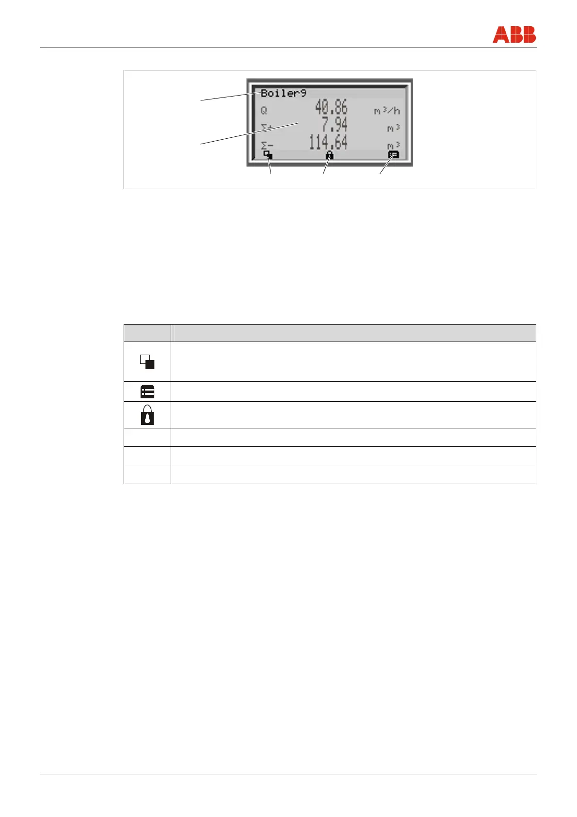
Fig. 49: Process display (example)
1 Measuring point identifier
2 Current process values
3 Symbol indicating button function
4 Symbol indicating "Parameterization
protected"
The process display appears on the LC display when the device is switched on. It shows
information about the device and current process values.
The way in which the current process values (2) are shown can be adjusted on the configuration
level.
6.3.1.1 Description of symbols
Symbol Description
Call up information level.
When Autoscroll mode is enabled, a symbol appears here and the operator
pages are automatically displayed one after the other.
Call up configuration level.
The device is protected against changes to the parameter settings.
Q
Display of the current flowrate
Σ+
Totalizer status in forward direction
Σ-
Totalizer status in reverse direction

 Loading...