Electrical connections
42 - EN FEX300, FEX500 CI/FEX300/FEX500-EN
5.6.2 Devices with PROFIBUS PA or FOUNDATION fieldbus
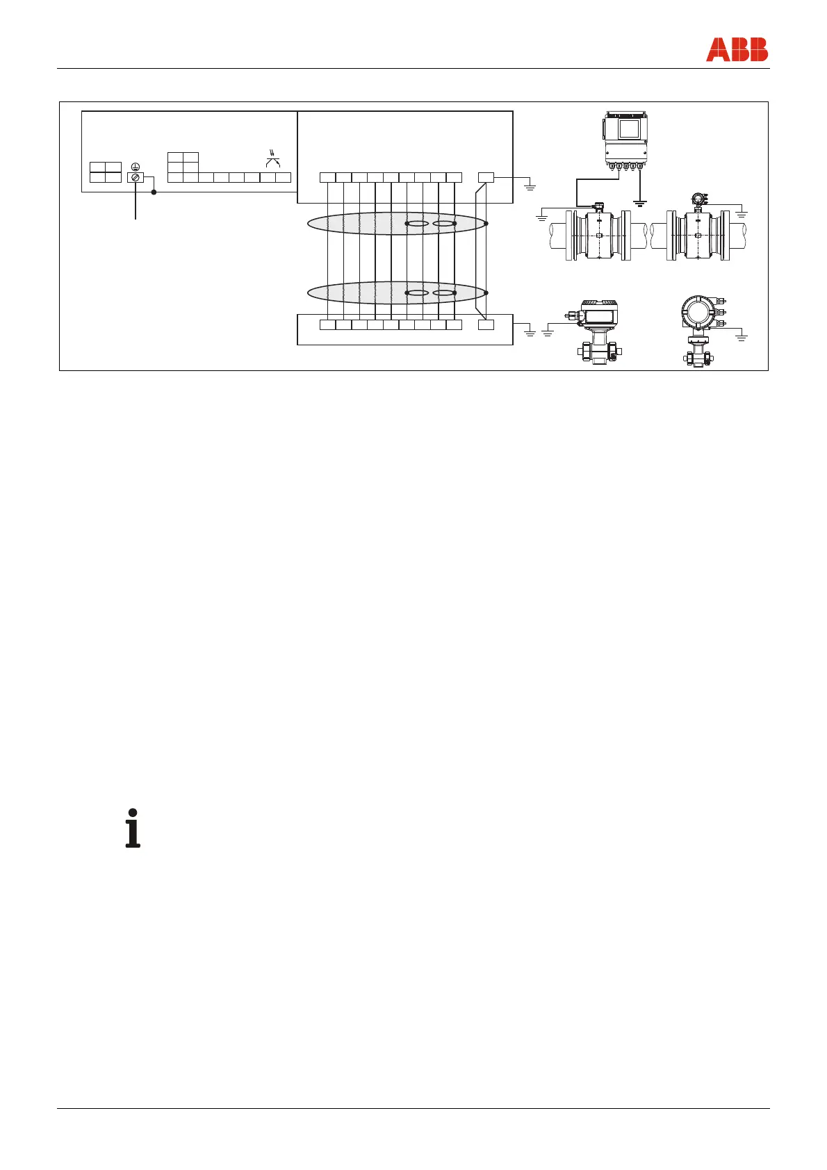
G01032
A
51 52 81 82
41 42
L N
1+ 2-
M1 M2 D1 D2
3
2S
E2 E1
1S
M1 M2 D1 D2
3
2S
E2 E1
1S SE
B
{
{
{
{
{
23
4
5
1
PE
78910
11 12
13
6
6
< 50 m (200 m)
< 164ft(656 ft)
SE
+
-
97 98
PA+ PA-
FF+ FF-
Fig. 39
A Transmitter
B Flowmeter sensor
1 Power supply
See name plate
2
Digital communication (terminal 97 / 98)
• PROFIBUS PA in acc. with IEC 61158-2 (PA+ / PA-)
U = 9 ... 32 v, I = 10 mA (normal operation), I = 13 mA (in the event of an error / FDE)
Bus connection with integrated protection against polarity reversal
The bus address can be set via the DIP switches in the device (with dual-compartment transmitter housing only), the transmitter
display or the fieldbus.
or
• FOUNDATION fieldbus in acc. with IEC 61158-2 (FF+ / FF-)
U = 9 ... 32 v, I = 10 mA (normal operation), I = 13 mA (in the event of an error / FDE)
Bus connection with integrated protection against polarity reversal
3 Not assigned
4 Not assigned
5 Digital output DO2 (terminals 41 / 42) (pulse output or digital output)
Function can be configured locally as "Pulse Output" or "Digital Output" using software.
Factory setting is "Digital Output", flow direction signaling.
The output is always a "passive" output (optocoupler).
Data for the optocoupler: U
max
= 30 V, I
max
= 220 mA, f
max
≤ 5250 Hz
6 Functional ground
7 Brown
8 Red
9 Orange
10 Yellow
11 Green
12 Blue
13 Violet
Important (Note)
For detailed information about grounding the transmitter and the flowmeter sensor, please refer to the section titled
"Installation / grounding".

 Loading...