Electrical connections
30 - EN FEX300, FEX500 CI/FEX300/FEX500-EN
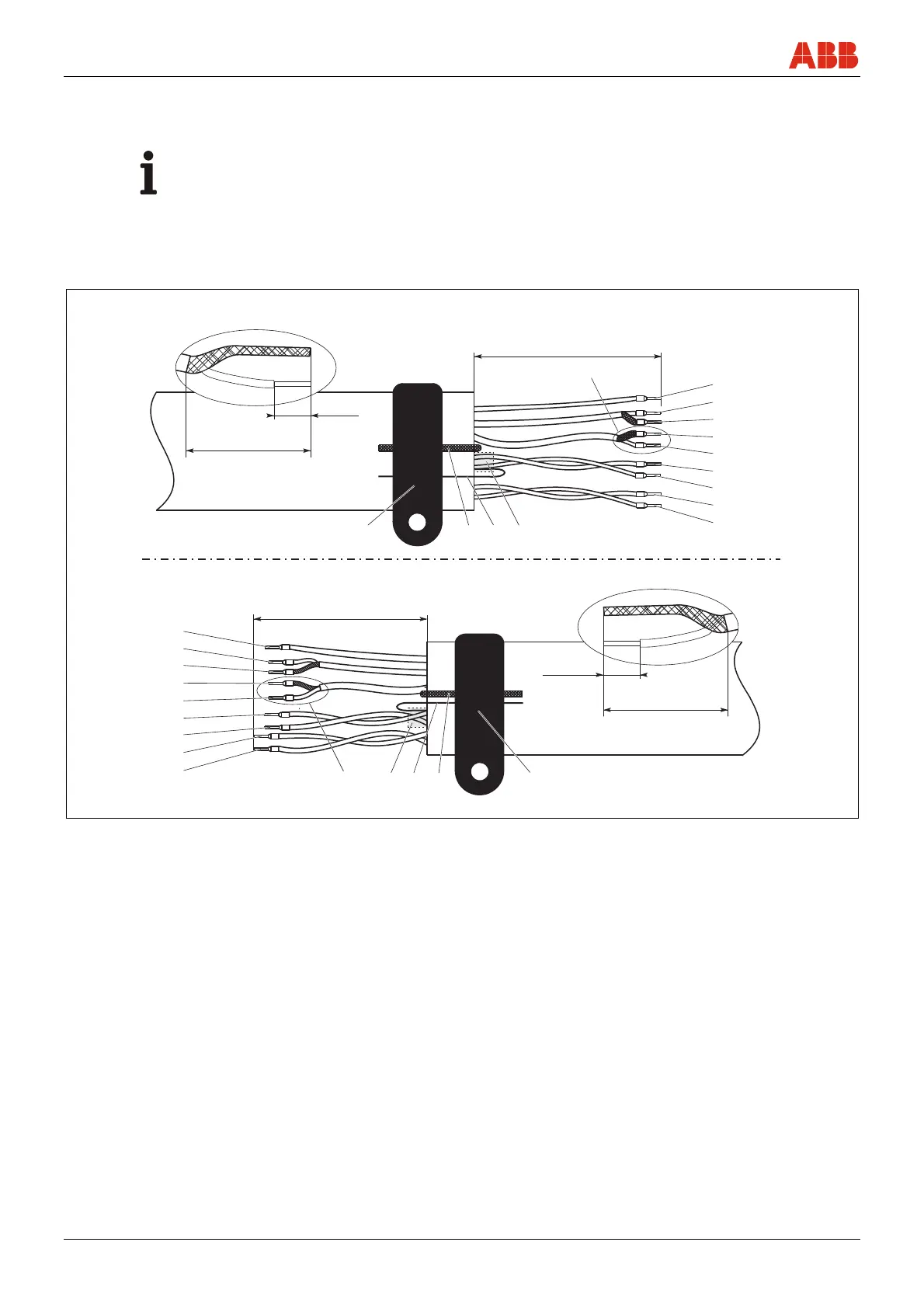
5.2.2 Cable with part number D173D031U01
Prepare both cable ends as shown.
Important (Note)
Use wire end sleeves.
• Wire end sleeves 0.75 mm
2
(AWG 19), for shielding (1S, 2S)
• Wire end sleeves 0.5 mm
2
(AWG 20), for all other wires
The shields may not touch (signal short circuit).
Flowmeter sensor side
G01030-01
X
L
2
1
2
3
4
5
6
7
8
9
10 11 12 13
8 (0.31)
25 (0.98)
"X"
70 (2.76)
1
2
3
4
5
6
7
8
9
13 12 11 10
X
8 (0.31)
25 (0.98)
"X"
Transmitter side
Fig. 28: Flowmeter sensor side, dimensions in mm (inch)
1 Measurement potential 3, green L2 = 70 (2.76)
2 Signal line E1, violet L2 = 60 (2.36)
3 Shield 1S L2 = 60 (2.36)
4 Shield 2S L2 = 60 (2.36)
5 Signal line, E2, blue L2 = 60 (2.36)
6 Data line, D2, yellow L2 = 70 (2.76)
7 Data line, D1, orange L2 = 70 (2.76)
8 Magnet coil, M2, red L2 = 90 (3.54)
9 Magnet coil, M1, brown L2 = 90 (3.54)
10Foil shield (D1, D2)
11Foil shield continuity wire (D1, D2)
12Ground wire, steel
13SE clamp

 Loading...