Do you have a question about the ABB ProcessMaster and is the answer not in the manual?
| Type | Electromagnetic Flowmeter |
|---|---|
| Liner Material | PTFE, PFA, Polyurethane, Rubber |
| Electrode Material | Stainless steel, Hastelloy, Tantalum, Titanium, Platinum |
| Process Connection | Flange, Wafer |
| Fluid Temperature | -40 to 180 °C (-40 to 356 °F) Depending on liner |
| Output | 4-20 mA, HART, PROFIBUS PA, FOUNDATION Fieldbus |
| Power Supply | 100 to 230 V AC, 24 V AC/DC |
| Protection Class | IP67 |
| Approvals | ATEX, IECEx, FM, CSA |
Provides essential safety information and notes for careful reading of the manual.
Defines the approved applications and operational purposes of the device.
Details actions that constitute improper use, highlighting potential risks.
Specifies required qualifications for personnel involved in installation and operation.
Details safety, warning, and note symbols and their meanings.
Provides critical safety guidelines to be followed during device transport.
Outlines essential safety precautions and requirements for device installation.
Details mandatory safety procedures for electrical connections and installation work.
Specifies safety rules and warnings crucial for the safe operation of the device.
Lists the operational and technical limits that must be adhered to for safe use.
Identifies the specific types of fluids approved for measurement with this device.
Provides instructions and procedures for returning the device for service or repair.
Offers guidance on product disposal and compliance with WEEE and RoHS directives.
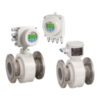
Describes the integrated transmitter and sensor design for compact models.
Details the remote mount design with separate transmitter and sensor connected via cable.
Instructs users to inspect devices for any damage that may have occurred during transit.
Provides safe handling and lifting guidance for transporting smaller flanged units.
Details safe handling and transport methods for larger flanged units.
Provides general guidelines and critical points to observe during the installation process.
Offers guidance on proper support for larger meter sizes to prevent housing damage.
Step-by-step instructions for the correct installation of the measuring tube.
Specifies the correct tightening torque values for various flange connections.
Provides tightening torque values for flange connections for ProcessMaster and HygienicMaster.
Lists tightening torque values specific to variable process connections on HygienicMaster.
Details EHEDG conformity requirements and associated warnings for hygienic installations.
Provides information and installation requirements for achieving 3A conformity.
Outlines critical requirements for optimal device installation and performance.
Specifies the correct flow direction for installation to ensure accurate measurement.
Guidance on the proper horizontal positioning of the electrode axis for accurate readings.
Details requirements for inlet and outlet pipe sections to ensure proper flow profiling.
Provides instructions for vertical installation, particularly for abrasive fluids.
Details horizontal installation steps, emphasizing maintaining a full meter tube.
Recommendations to prevent air pockets and ensure a consistently full meter tube.
Advises on using bypass connections for handling strongly contaminated fluids.
Offers guidance on mitigating vibration effects when installing near pumps.
Provides instructions for installing the high temperature design with thermal insulation.
Notes on specific installation conditions required for devices with advanced diagnostics.
Guidance for installing in larger diameter pipelines, including pressure loss calculations.
Provides essential information and procedures for grounding the device correctly.
Outlines general principles and important considerations for device grounding.
Details the grounding process for metal pipes with fixed flanges.
Describes the grounding procedure for metal pipes utilizing loose flanges.
Provides grounding instructions for plastic, non-metallic, or lined pipes.
Specific grounding instructions for the HygienicMaster sensor type.
Explains the function of protective plates for grounding and protection.
Describes the grounding method using conductive PTFE grounding plates.
Guidance on routing signal and coil cables, including shielding and distance considerations.
Instructions for preparing signal and magnet coil cables for dual-compartment transmitters.
Steps for preparing the D173D027U01 cable for dual-compartment transmitter connections.
Steps for preparing the D173D031U01 cable for dual-compartment transmitter connections.
Instructions for preparing signal and magnet coil cables for single-compartment transmitters.
Steps for preparing the D173D027U01 cable for single-compartment transmitter connections.
Steps for preparing the D173D031U01 cable for single-compartment transmitter connections.
Details on connecting the transmitter, including power supply and wiring.
Instructions for connecting the power supply, including breaker and wiring requirements.
Shows power supply terminal locations for dual-compartment transmitter housings.
Shows power supply terminal locations for single-compartment transmitter housings.
Explains how to connect signal and magnet coil cables to transmitter housings.
Provides instructions for connecting the flowmeter sensor to the transmitter.
Instructions for connecting the sensor via a metal terminal box.
Instructions for connecting the sensor via a plastic terminal box.
Guidance on connecting via cable conduit and preventing moisture ingress.
Details IP 68 protection class and connection requirements for submersion.
Procedure for sealing the connection box using a sealing compound.
Illustrates terminal connections for various communication protocols and peripherals.
Terminal connection diagrams specific to devices using the HART protocol.
Terminal connection diagrams for PROFIBUS PA and FOUNDATION fieldbus devices.
Illustrates connection examples for peripherals with current and digital outputs.
Lists essential checks to perform before initiating the commissioning process.
Describes device operation using the LCD display and capacitive control buttons.
Explains how to navigate through the device's menu system using control buttons.
Details the specific functions assigned to each control button for menu interaction.
Describes the device's menu structure: Process display, Information, and Configuration levels.
Explains the process display, showing current values and relevant symbols.
Details the various symbols displayed and their respective meanings.
Explains the format, classification, and meaning of LCD error messages.
Describes how to access detailed error descriptions from the information level.
Details on configuring the current output mode (active/passive) based on device type.
Configuration of output settings for dual-compartment transmitters using jumpers.
Configuration of output settings for single-compartment transmitters using jumpers.
Guides through the essential steps for commissioning the flowmeter unit.
Procedure for downloading system data, calibration, and transmitter settings.
Troubleshooting steps for resolving 'Incompatible sensor' error messages during setup.
Guide to using the 'Easy Set-up' menu for quick and efficient device configuration.
Overview of parameters accessible through the 'Easy Setup' menu for quick configuration.
Details on device information, sensor parameters, calibration data, and properties.
Covers device setup parameters like analog range, transmitter settings, and access control.
Parameters related to sensor configuration, including Qmax, span, and location tags.
Parameters for transmitter configuration, units, and low flow cut-off settings.
Parameters for display settings, including language, contrast, and operator page configuration.
Configuration of digital outputs, alarm settings, and signal types for inputs/outputs.
Settings for pulse output modes, pulses per unit, pulse width, and frequency.
Configuration options for digital inputs, such as totalizer reset and alarm signals.
Parameters for setting current output modes, alarm thresholds, and output behavior.
Configuration of process alarms, including masking, simulation, and history.
Settings for communication protocols like HART and PROFIBUS PA, including device address.
Overview of diagnostic functions, including detectors, measurements, and grounding checks.
Controls for diagnostic functions, such as Empty Pipe Detector and Sensor Measurements.
Settings for totalizers, batching, and editing volume totals.
General notes on extended diagnostic functions, their availability, and initial activation.
Detects partially filled flowmeter sensors and outputs an alarm via digital output.
Detects gas bubbles in fluid, triggering an alarm based on adjustable limit values.
Detects electrode coatings by monitoring limit values and triggers an alarm.
Monitors fluid conductivity against set limits, triggering alarms as needed.
Monitors electrode impedance to detect shorts or leakage, triggering alarms.
Includes monitoring of sensor temperature and coil resistance for diagnostics.
Monitors the temperature of the flowmeter sensor coils using adjustable limit values.
Monitors the resistance of the flowmeter sensor's coils against adjustable limits.
Stores measured values cyclically for trend analysis using internal memory.
Compares current recorded values with factory calibration or commissioning values.
Function to perform an electrical grounding check on the device.
Step-by-step guide to perform the grounding check and interpret the power spectrum results.
Provides recommended limit values for various diagnostic parameters for initial setup.
Recommended limit values for monitoring coil resistance based on fluid temperature.
Recommended limit values for detecting electrode deposits based on QE values.
Recommended limit values for monitoring electrode impedance based on average impedance.
Recommended settings for the Trend Logger, specifically the logtime interval.
Lists other relevant documents, datasheets, and interface descriptions for the product.
Details the CE mark, explosion protection standards, and other relevant approvals.