Commissioning
52 - EN FEX300, FEX500 CI/FEX300/FEX500-EN
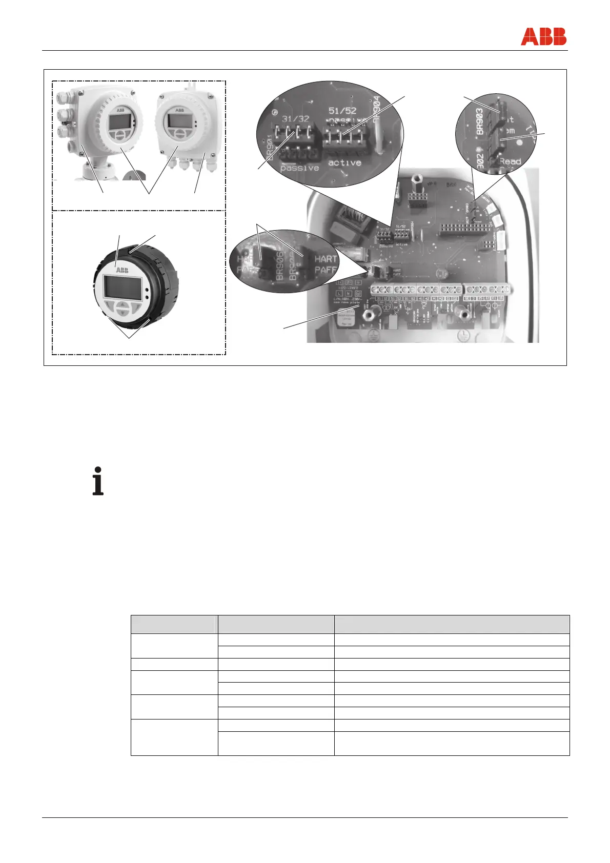
6.4.2 Transmitter with single-compartment housing
G01321
„A“ „B“
1
2 3
3
4
6
5
7 8
9
Fig. 51: Jumpers in the single-compartment housing
A Integral mount design
B Remote mount design
1 Housing cover
2 Transmitter plug-in module
3 Fixing screws
4 Backplane (in the transmitter housing)
5 Jumpers (BR905, BR906) for communication
6 Jumper (BR901) for active / passive current output
7 Jumper (BR904) for active / passive pulse output
8 Jumper (BR903) for integral / remote mount design
9 Jumper (BR902) for hardware write protection
Important (Note)
The backplane is mounted in the transmitter housing (not the transmitter plug-in module).
Configure the outputs as follows:
1. Switch off power supply.
2. Open the housing cover.
3. Remove the mounting screws for the transmitter electronics unit
4. Pull out the transmitter electronics unit
5. Set jumpers on backplane in accordance with the following table.
Jumper Number Function
BR901 active Current output 31 / 32 active
passive Current output 31 / 32 passive
BR902 Read only Hardware write protection active
BR903 integral Transmitter with integral mount design
remote Transmitter with remote mount design
BR904 active Pulse output 51 / 52 active
passive Pulse output 51 / 52 passive
BR905, BR906 HART Digital communication via HART protocol
PA/FF Digital communication via PROFIBUS PA or
FOUNDATION Fieldbus
6. Install the transmitter in reverse order.

 Loading...