Electrical connections
CI/FEX300/FEX500-EN FEX300, FEX500 EN - 43
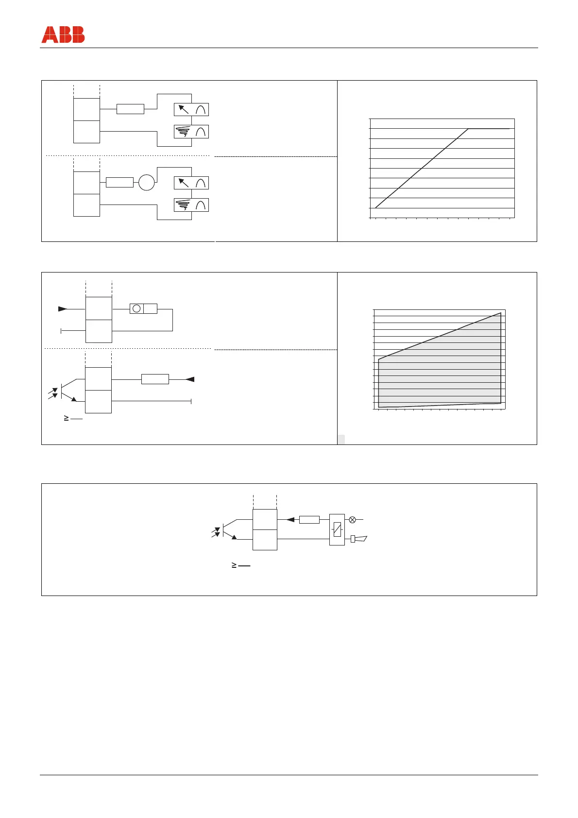
5.6.3 Connection examples for the peripherals
Current output
Max. permissible load (R
B
) as a function of the source
voltage (U
2
)
A = "Active" configuration:
4 ... 20 mA, HART
Load: 0 =R = 650 Ω (300 Ω for
Ex Zone 1 / Div. 1)
Min. load with HART: 250 Ω
G00475
+31
-32
I E
+31
-32
I E
V
A
B
R
B
R
B
U
1
U
2
B = "Passive" configuration:
4 ... 20 mA, HART
Load: 0 =R = 650 Ω
Min. load with HART: 250 Ω
Supply voltage for the current
output, terminals 31 / 32:
U1: Min. 11 V, max. 30 V
I = internal, E = external
G00592
200
250
300
350
400
450
500
550
600
650
700
17 18 19 20 21 22 23 24 25 26 27 28 29 30
U [V]
2
R[ ]
B
Ω
Fig. 40
Digital output DO1
Max. permissible load (R
B
) as a function of the source
voltage (U
2
)
A = "Active" configuration
19 ... 21 V+
-
IE
51
52
R
B
*
I
max
= 220 mA
≤
30 V+
-
R
B
*
U
CE
I
CE
IE
51
52
G00476-03
A
B
U
2
B = "Passive" configuration
G00593
50
150
250
350
450
550
650
750
850
950
1050
1150
1250
1350
1450
1550
16 17 18 19 20 21 22 23 24 25 26 27 28 29 30
U [V]
2
R[ ]
B
Ω
I = internal, E = external = Permissible range
Fig. 41
Digital output DO2, e.g., for system monitoring, max. / min. alarm, empty meter tube or forward / reverse signal, or counting pulses
(function can be configured using software)
G00792
R
B
*
I
max
= 220 mA
R
B
*
U
CE
I
CE
+U+U
I E
41
42
I = internal, E = external
Fig. 42

 Loading...