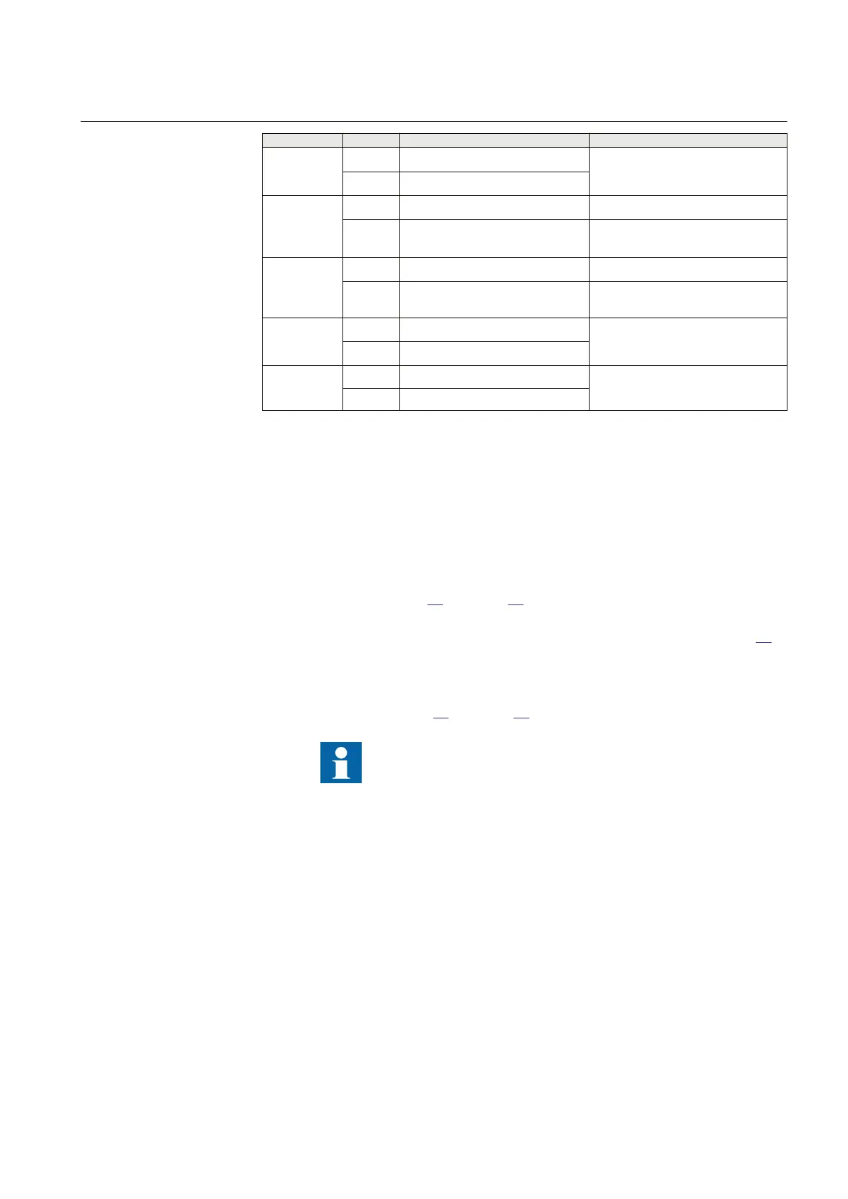
Test point Reach Value Comments
9 X –0.8 x RLdFw
set
x tan(ArgDir=20°)
R 0.8 x RLdFw
set
10 X 0.17 x (2 x X1
set
+ X0
set
) Exact: 0.5 x (2 x X1
set
X0
set
)/3
R -0.36 x (2 x X1
set
+ X0
set
) Exact: 0.5 x (2X1
set
+ X0
set
)/(3 x
tan(AgNegDir=30°)
11 X 0.27 x (2 x X1
set
+X0
set
) Exact: 0.8 x (2 x X1
set
+ X0
set
)/3
R
–0.57 x (2 x X1
set
+ X0
set
) Exact: 0.8 x (2X1set + X0set)/(3 x
tan(AgNegDir=30°)
12 X 0.5 x (2 x X1
set
+ X0
set
)/3
R 0.5 x (2 x R1
set
+ R0
set
)/3
13 X 0 Only used when RLdFw > RFPE
R RFPE
11.4.1.1 Measuring the operating limit of set values
M14944-126 v8
Procedure:
1. Subject the
IED to healthy normal load conditions for at least two seconds.
2. Apply the fault condition and slowly decrease the measured impedance to
find the operating value of the phase-to-phase fault for zone 1 according to
test point 1 in figure
23 and table 20. Compare the result of the measurement
with the set value.
3.
Repeat steps 1 to 2 to find the operating value for test points
2, 3 in table
20.
Observe that the zones that are not tested have to be blocked and the zone that
is tested has to be released.
4. Repeat steps 1 to 3 to find the operating value for the
phase-to-earth fault L3–
E according to figure
24 and table 21.
Test points 8, 9. 10 and 11 are intended to test the directional
lines of impedance protection. Since directionality is a
common function for all 5 measuring zones, it is only
necessary to test point
s 8, 9. 10 and 11 once in the forward
direction in order to test the accuracy of directionality
(directional angles). Directional functionality testing (trip
inside, no-trip outside) should always be made for all
impedance zones set with directionality (forward or reverse).
11.4.1.2 Measuring the operating time of distance protection zones
M14944-154 v6
Procedure:
1MRK 505 378-UEN A Section 11
Testing functionality by secondary injection
Line differential protection RED670 2.2 IEC 117
Commissioning manual

 Loading...


