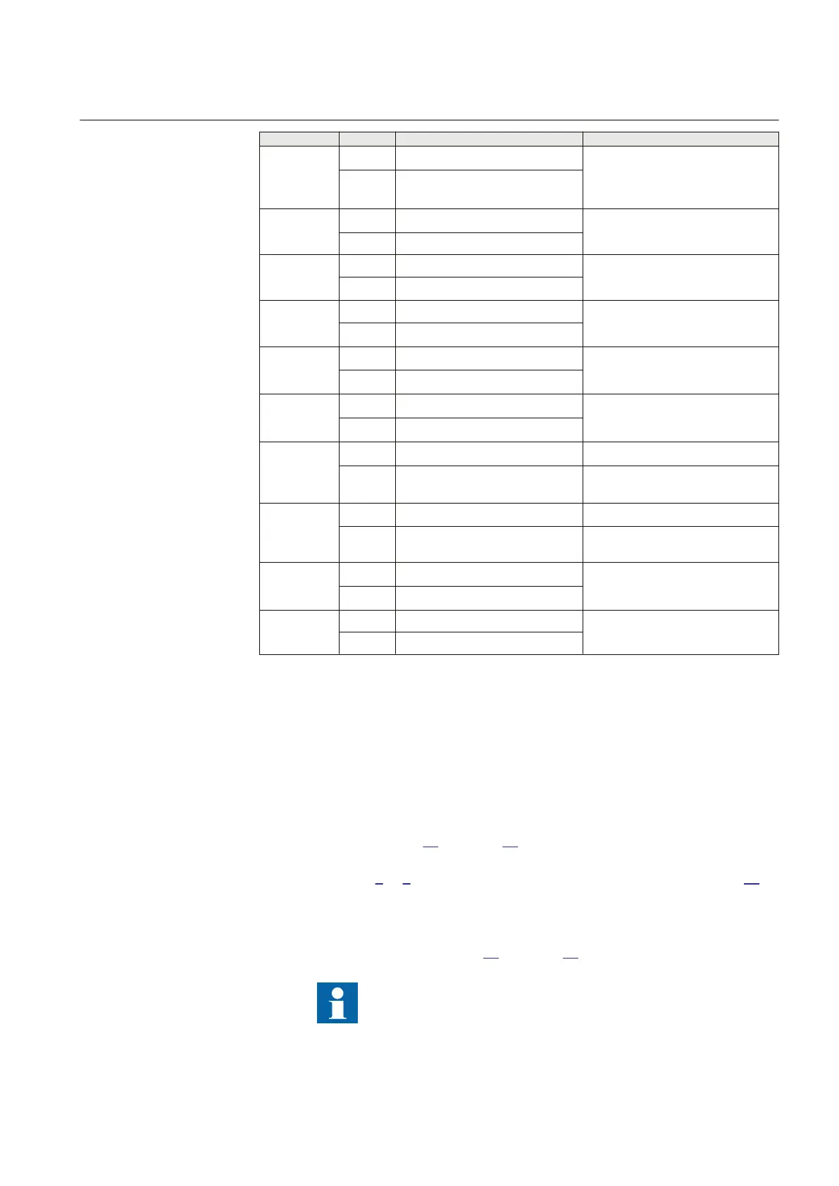
Test point Reach Value Comments
4 X 0.5 x (2 x X1
set
+ R0
set
)/3
R 0.5 x (2 x R1
set
+R0
set
)/3 +
RFPE
set
5
X 0.85 x RFPE
set
x tan(ArgLdset) ArgLd = angle for the maximal load
transfer.
R 0.85 x RFPE
6 X RLdFwset x tan(ArgLdSet)
R RLdFw
set
7 X 0
R RLdFw
set
8 X –02143 x RLdFw
set
Exact: 0.8 x RFPE x tan (ArgDir)
R 0.8 x RLdFw
set
9 X –0.8 x RLdFw
set
x tan(ArgDir)
R 0.8 x RLdFw
set
10 X 0.17 x (2 x X1
set
+ X0
set
) Exact: 0.5 x (2 x X1
set
X0
set
)/3
R
-0.36 x (2 x X1
set
+ X0
set
) Exact: 0.5 x (2X1
set
+ X0
set
)/(3 x
tan(AgNegDir90)
11 X 0.27 x (2 x X1
set
+X0
set
) Exact: 0.8 x (2 x X1
set
+ X0
set
)/3
R
–0.57 x (2 x X1
set
+ X0
set
) Exact: 0.8 x (2X1set + X0set)/(3 x
tan(AngNegDir 90))
12 X 0.5 x (2 x X1
set
+ X0
set
)/3
R 0.5 x (2 x R1
set
+ R0
set
)/3
13 X 0
R RFPE
11.4.5.1 Measuring the operating limit of set values
GUID-02EE80DB-CE52-49F0-99C4-14FD84766009 v3
Procedure:
1. Subject the
IED to healthy normal load conditions for at least two seconds.
2. Apply the fault condition and slowly decrease the measured impedance to
find the operating value of the phase-to-phase fault for zone 1 according to
test point 1 in figure
29 and table 26. Compare the result of the measurement
with the set value.
3. Repeat steps 1 to 2 to find the operating value for test points 2, 3 in table26.
Observe that the zones that are not tested have to be blocked and the zone that
is tested has to be released.
4. Repeat steps 1 to 3 above to find the operating value for the
phase-to-earth
fault L3-E according to figure
30 and table 27.
Test points 8, 9, 10 and 11 are intended to test the directional
lines of impedance protection. Since directionality is a
common function for all 5 measuring zones, it is only
1MRK 505 378-UEN A Section 11
Testing functionality by secondary injection
Line differential protection RED670 2.2 IEC 127
Commissioning manual

 Loading...


