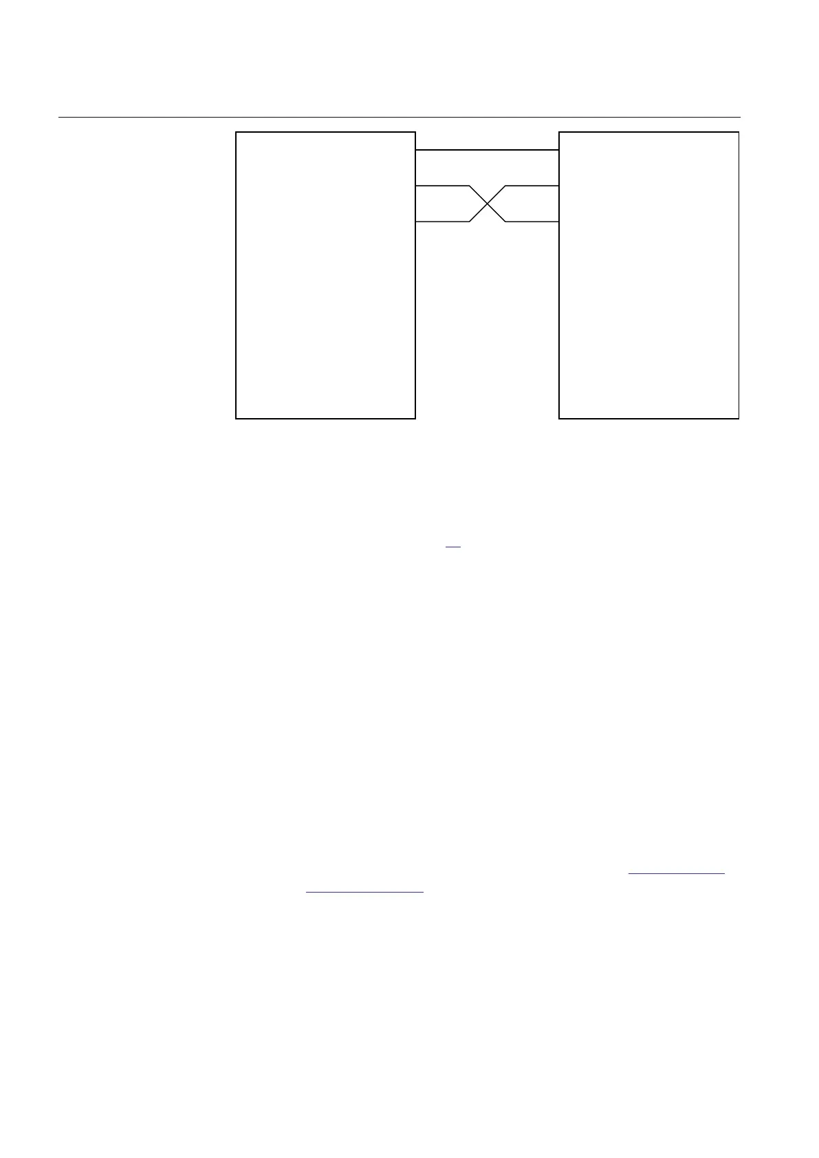
I E D T E S T S E T
IL 1
IL 2
IL 3
IL 1
IL 2
IL 3
IED
IEC10000013-1-en.vsd
IEC10000013 V1 EN-US
Figure 55: Connection of test equipment to the IED
1. Connect the test set for three-phase current injection to the appropriate IED
terminals as shown in Figure
55
2. Increase the injected current and note the operated value (
start value) of the
studied step of the function.
3. Decrease the current slowly and note the reset value.
4. Connect a trip output contact to a timer.
5. Set the injected current to 200% of the operate level of the tested stage.
Switch on the current and check the time delay.
6. Check that all trip and start contacts operate according to the configuration
(signal matrices).
7. Finally check that start and trip information is stored in the event memory.
Completing the test
Continue to test another function or end the test by changing the TESTMODE
setting to Off. Restore connections and settings to their original values, if they were
changed for testing purposes.
11.11.7.8 Zero sequence overcurrent protection LCZSPTOC
GUID-DF48CC20-7275-4543-84D1-0856A946520A v2
Prepare the IED for verification of settings as outlined in section
"Requirements"
and section "Preparing for test" in this chapter.
Section 11 1MRK 505 378-UEN A
Testing functionality by secondary injection
254 Line differential protection RED670 2.2 IEC
Commissioning manual

 Loading...


