9.6 Optical budget calculation for PMU - PDC
communication
GUID-F5DEACB1-4B83-4C68-B59A-694CAC78AF3D v3
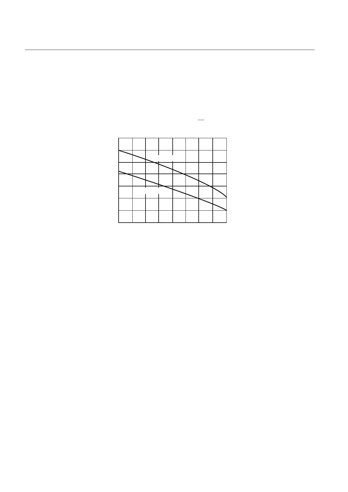
Most of the times, the PMU IEDs are located in the substations. A local PDC might
be located in the substation. For communications within the substation or between
the IED and the W
AN/LAN access point, it is important to know what is the optical
budget available. The graph in Figure 18 shows the dynamic range available for a
PMU – PDC configuration using typical OEMs.
14
12
10
8
6
4
2
0
0
0.5 1.0
1.5
2.0
2.5
3.0 3.5 4.0
62.5/125 µm
50/125 µm
O
P
B
–
O
P
T
IC
A
L
P
O
W
E
R
B
U
D
G
E
T
- d
B
FIBER OPTIC CABLE LENGTH - km
IEC11000409_1_en.vsd
IEC11000409 V1 EN-US
Figure 18: Optical power budget for fiber optic cable lengths
As shown in the graph, if one uses a 62.5/125 µm fiber, the value under the
62.5/125 µm curve represents the remaining optical budget at any link length,
which is available for overcoming non-fiber cable related losses.
Losses in the connectors and splices are typically 0.3dB/connection. The user must
reserve 3dB spare for the uncertainty of the measurements.
Section 9 1MRK 505 378-UEN A
Establishing connection and verifying the IEEE C37.118/1344 communication
86 Line differential protection RED670 2.2 IEC
Commissioning manual

 Loading...


