shown in the right-hand side in figure 52) in order to put 110 kV & 36.75 kV currents
in phase.
T
o ensure proper application of the IED for this power transformer it is necessary to do
the following:
1. Check that HV CTs are connected to 1 A CT inputs in the IED.
2. Check that LV CTs are connected to 5 A CT inputs in the IED.
3. When delta connected CTs are used make sure that both CT sets are identically
connected (that is, either both DAC or both DAB).
4. For wye connected CTs make sure how they are 'star'red (that is, grounded) towards
or away from the protected transformer.
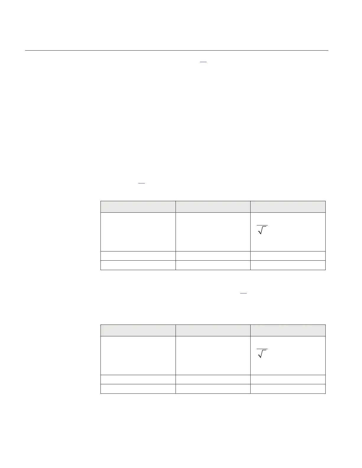
5. Enter the following settings for all three CT input channels used for the HV side
CTs, see table
20.
Table 20: CT input channels used for the HV side CTs
Setting parameter Selected value for both solution 1
(wye connected CTs)
Selected value for both Solution 2
(delta connected CTs)
CTprim 200
EQUATION1891 V1 EN-US (Equation 16)
CTsec 1 1
CT_WyePoint FromObject ToObject
To compensate for delta connected CTs, see equation 16.
6. Enter the following settings for all three CT input channels used for the LV side CT
s
Table 21: CT input channels used for the LV side CTs
Setting parameter Selected value for both Solution 1
(wye connected)
Selected value for both Solution 2
(delta connected)
CTprim 500
EQUATION1892 V1 EN-US (Equation 17)
CTsec 5 5
CT_WyePoint ToObject ToObject
Section 7 1MRK 504 163-UUS A
Differential protection
154 Transformer protection RET670 2.2 ANSI
Application manual

 Loading...


