U
C
X
C
0
0.02 0.04 0.06 0.08 0.1 0.12 0.14 0.16 0.18 0.2
-2
0
2
0 0.02 0.04 0.06 0.08 0.1 0.12 0.14 0.16 0.18 0.2
-5
0
5
0 0.02 0.04 0.06 0.08 0.1 0.12 0.14 0.16 0.18 0.2
-50
0
50
0 0.02 0.04 0.06 0.08 0.1 0.12 0.14 0.16 0.18 0.2
-40
-20
0
I
L
I
V
0 0.02 0.04 0.06 0.08 0.1 0.12 0.14 0.16 0.18 0.2
-2
2
0 0.02 0.04 0.06 0.08 0.1 0.12 0.14 0.16 0.18 0.2
-5
5
0 0.02 0.04 0.06 0.08 0.1 0.12 0.14 0.16 0.18 0.2
-50
50
0 0.02 0.04 0.06 0.08 0.1 0.12 0.14 0.16 0.18 0.2
-40
-20
0
0
0
0
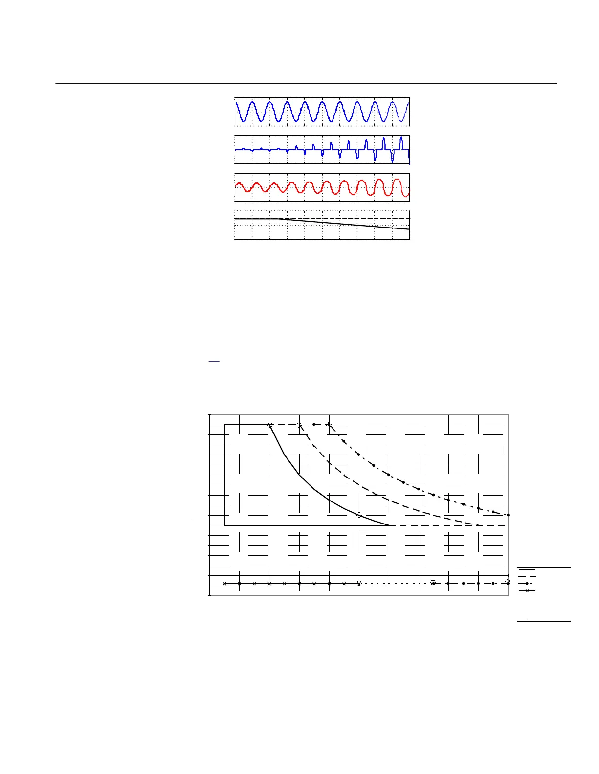
IEC06000597 V1 EN-US
Figure 90: TCSC wave forms presented in capacitive boost mode for a typical
50Hz system
The apparent impedance of the TCSC (the impedance seen by the power system) can
typically be increased to up to 3 times the physical impedance of the capacitor, see
figure
91. This high apparent reactance will mainly be used for damping of power
oscillations.
Imperatriz TCSC, Operating range
-0.4
-0.2
0
0.2
0.4
0.6
0.8
1
1.2
1.4
1.6
1.8
2
2.2
2.4
2.6
2.8
3
3.2
0 300 600 900 1200 1500 1800 2100 2400 2700 3000
Continuous
30 min. overload
10s overload
Bypass mode
Series5
IEC06000598 V1 EN-US
Figure 91: Operating range of a TCSC installed for damping of power oscillations
(example)
1MRK 504 163-UUS A Section 8
Impedance protection
Transformer protection RET670 2.2 ANSI 213
Application manual

 Loading...


