322 34980A User’s Guide
13 Breadboard Module
Dimension Information for the Custom PC Board Area
Utilization of the empty space within the 34959A breadboard module is
left entirely up to the user. However, assuming you want to most fully
utilize the space provided, output signals through the Dsub ports, and
connect your board securely to the supplied ribbon cable headers, four
detailed dimension drawings are provided in this section to assist with
your PC board fabrication.
The figure on page 323 illustrates the external dimensions of the largest
PC board that will fit into the space provided, and provides distances on
the plane of that board from the datum to the following locations:
• The 15 PC board mounting holes in the sheet metal base.
• Pin 1 of the board mounting position for the 26- pin ribbon cable
connector carrying digital I/O signals and control power to/from
header P102.
• Pin 1 of the board mounting position for the 40- pin ribbon cable
connector carrying relay drive signals and control power from header
P101.
• The center of the two user- supplied Dsub output connectors.
• The mounting holes for the two Dsub connectors. Note that this
dimension, labelled “Dimension A” on the drawing, varies with the
selection of Dsub connector used (e.g., DB50, DB78M, DB78F).
The figure on page 324 shows the mounting footprints for the
recommended DB50(M/F) connectors. The two figures on page 325 show
the footprints for the recommended DB78M and DB78F connectors,
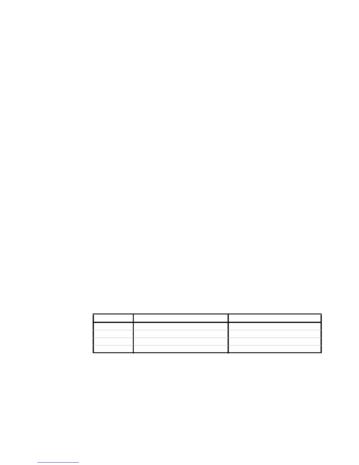
respectively. The part numbers for the recommended connectors are listed
in the following table:
Recommended Dsub Connectors as Shown in Dimension Drawings 2 through 4
The suggested supplier for the Dsub connectors is:
Vendor: Conec Corporation
Vendor Address: 343 Technology Drive, Garner, NC 27529 U.S.A.
Connector Agilent Part Number Conec Part Number
DB-50 (M) 1253-5853 161C18569X
DB-50 (F) 1253-5854 DSSEXSTCM39A
DB-78 (M) 1253-6006 DLH5XP8CK53X
DB-78 (F) 1253-6007 DLH5XS8CK53X

 Loading...


