Publication 1756-UM523F-EN-P - December 2006
48 Install the System
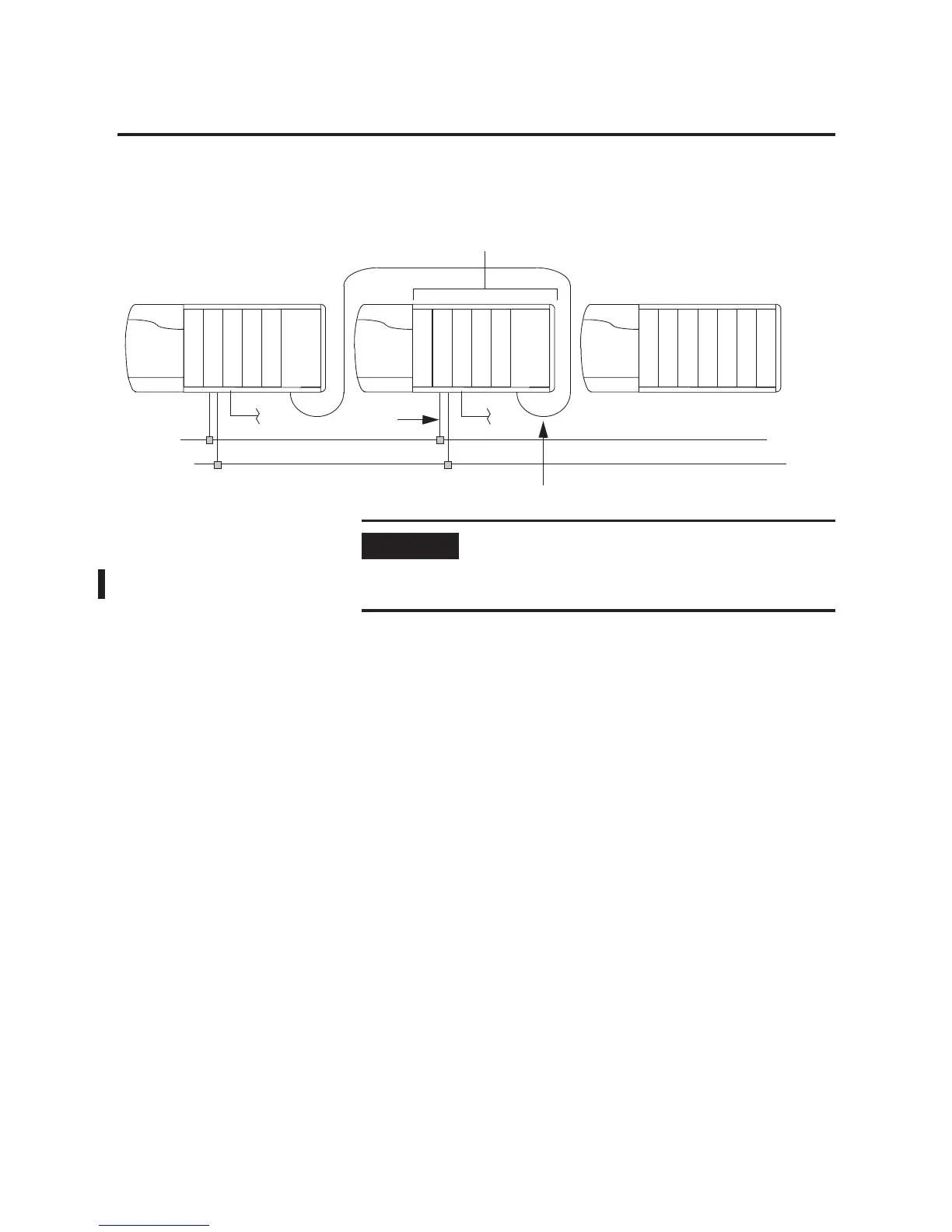
Install Modules in the
Second Redundant Chassis
1. For each module in the first redundant chassis, install an
identical module into the same slot of the second redundant
chassis.
2. Connect the CNB, ENBT, and EWEB modules to their respective
networks.
3. Connect one of these fiber optic cables to the 1757-SRM
modules:
• 1757-SRC1
• 1757-SRC3
• 1757-SRC10
• 1757-SRC50
• 1757-SRC100
2.
42800
L
5
5
S
R
M
C
N
B
1.
L
5
5
S
R
M
C
N
B
3.
E
N
B
T
E
N
B
T
IMPORTANT
• The modules in each redundant chassis must match each other
slot-by-slot.
• Set the rotary switches of the 1756-CNB/D/E or 1756-CNBR/D/E
modules for both redundant chassis to the same node address.

 Loading...
