166 Rockwell Automation Publication 22C-UM001J-EN-E - January 2017
Appendix D Application Notes
Example 1
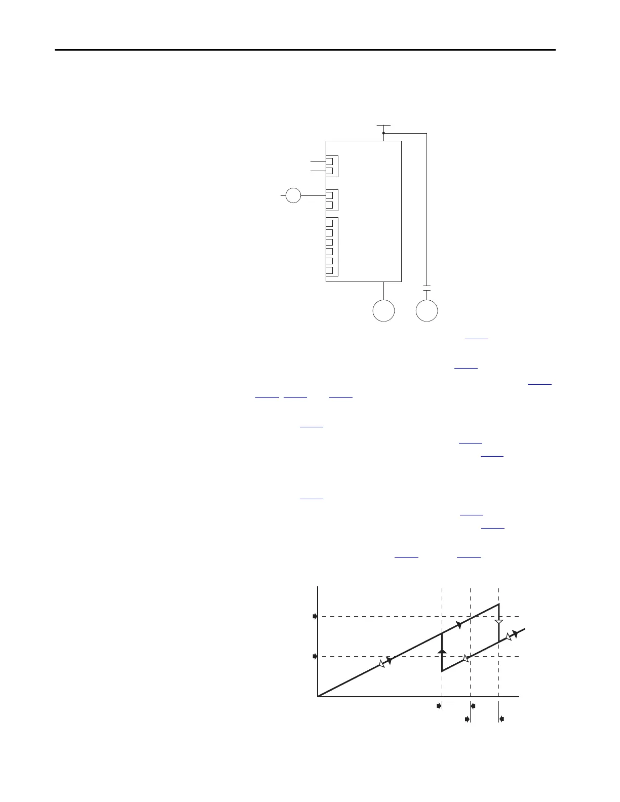
Figure 41 - One External Motor without AutoSwap
• Auxiliary Motor Control is enabled via Parameter R239 [Aux Motor
Mode].
• Number of auxiliary motors is set via Parameter R240
[Aux Motor Qty].
• Relays are configured for Auxiliary Motor Control via parameters T055
,
T060
, R222, and R225.
• The frequency of Motor #1 that Motor #2 turns on at is set via
Parameter R241
[Aux 1 Start Freq].
• The time that Motor #1 is above the value set by R241
[Aux 1 Start
Freq] before turning on Motor #2 is set via Parameter R250
[Aux Start
Delay].
• The frequency of Motor #1 that Motor #2 turns off at is set via
Parameter R242
[Aux 1 Stop Freq].
• The time that Motor #1 is below the value set by R242
[Aux 1 Stop
Freq] before turning off Motor #2 is set via Parameter R251
[Aux Stop
Delay].
• PID setup is done via Parameters A150
through A159. See Appendix D
for additional information.
PID
Reference
Feedback
Drive Relays
Auxiliary Relay Card
M2L
PowerFlex 400
Three-Phase Power
M2L
M1 M2
Frequency
R241 [Aux 1 Start Freq]
R251 [Aux Stop Delay]
R250 [Aux Start Delay]
R242 [Aux 1 Stop Freq]
Time
 Loading...