244 Rockwell Automation Publication 2094-UM001J-EN-P - March 2017
Appendix D Configure the Load Observer Feature
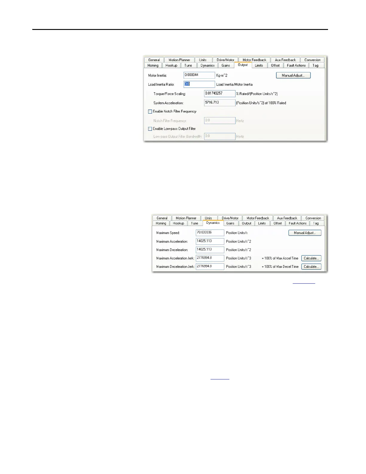
b. Enable Low-pass Output Filter = Unchecked
8. If required, reduce the Maximum Acceleration and Maximum
Deceleration values to meet application requirements and protect the
drive and motor from overload.
Acceleration limits, by default, are set to their maximum value,
providing the best performance for a Load Inertia Ratio of zero.
However, your application loads the motor and it will not be able to
accelerate as fast.
9. Refer to Compensate for High Frequency Resonances on page 251
, to
tune-out resonant frequencies.
Auto-tune Gain Settings
This procedure explains how to configure the load observer feature after
running Auto-tune. This method also works for any existing set of gains where
the Load Inertia Ratio is known or manually calculated, for example, when the
Load Inertia Ratio > 0.
1. Click the Tune tab in the Axis Properties dialog box and perform Auto-
tune.
For variable inertia loads, perform Auto-tune at the point of lowest
mechanical inertia. If you manually calculate the Load Inertia Ratio, use
the minimum load inertia.
TIP Try the out-of-box method before executing Auto-tune. Refer to Out-of-Box
Gain Settings on page 242
.

 Loading...


