54 Rockwell Automation Publication 2094-UM001J-EN-P - March 2017
Chapter 3 Mount the Kinetix 6000 Drive System
Mount Modules on the
Power Rail
Follow these steps to mount the IAM, AM, IPIM, shunt, and slot-filler
modules.
1. Remove the protective covers from the power rail connectors.
2. Determine the next available slot and module for mounting.
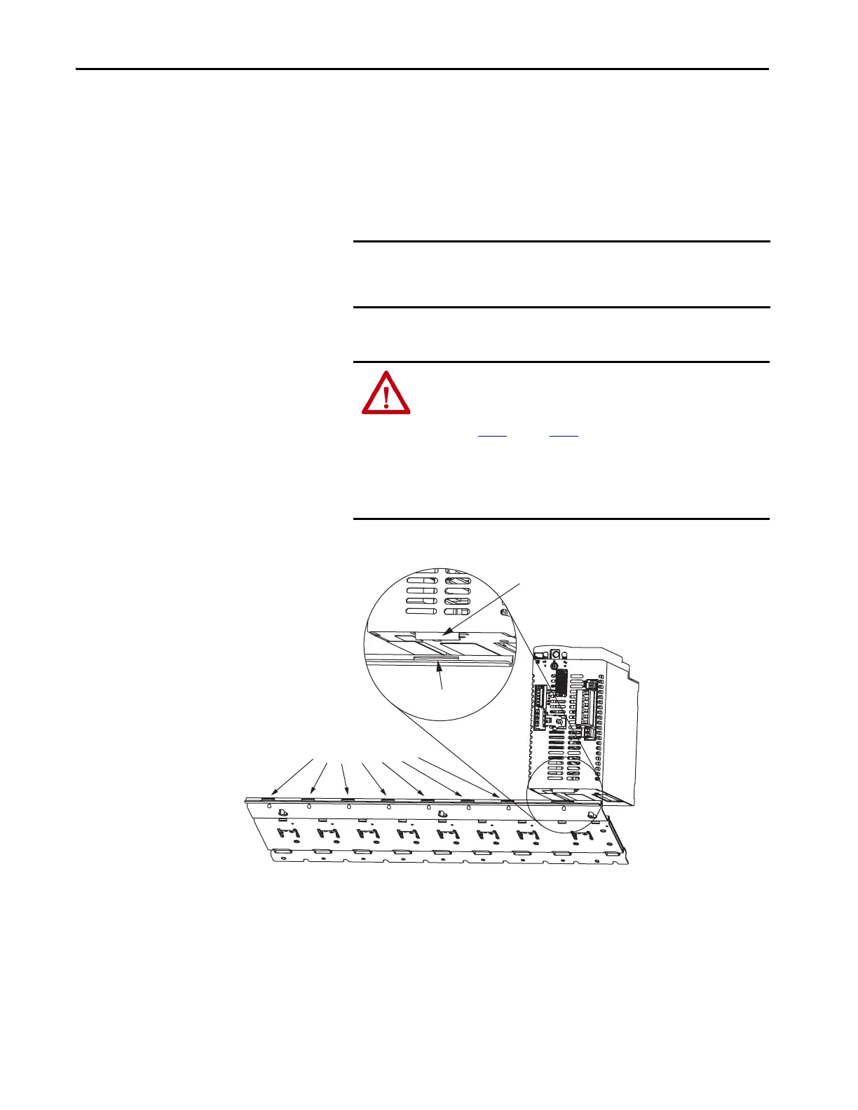
3. Hang the mounting bracket from the slot on the power rail.
TIP All modules mount to the power rail by using the same technique; however,
only the IAM module is used in the examples.
IMPORTANT The IAM module must be positioned in the leftmost slot of the
power rail. Position your axis modules, shunt module, and slot-filler
modules to the right of the IAM module.
ATTENTION: To avoid damage to the pins on the back of each IAM,
AM, IPIM, shunt, and slot-filler module and to make sure that
module pins mate properly with the power rail, hang modules as
shown in step 3
through step 6.
The power rail must be mounted vertically on the panel before
hanging modules on the power rail. Do not mount modules if the
power rail is horizontal.
Slots for additional axis modules,
shunt module, or slot-filler modules.
Power Rail Slot
Mounting Bracket
Power Rail
Kinetix 6000 IAM, AM, IPIM,
Shunt, or Slot-filler Module
(IAM module is shown)

 Loading...


