Rockwell Automation Publication 2094-UM001J-EN-P - March 2017 71
Connector Data and Feature Descriptions Chapter 4
Power and Relay
Specifications
This section provides a description of the Kinetix 6000 brake relay (BC), input
power (IPD), motor power (MP), and control power (CPD) connectors.
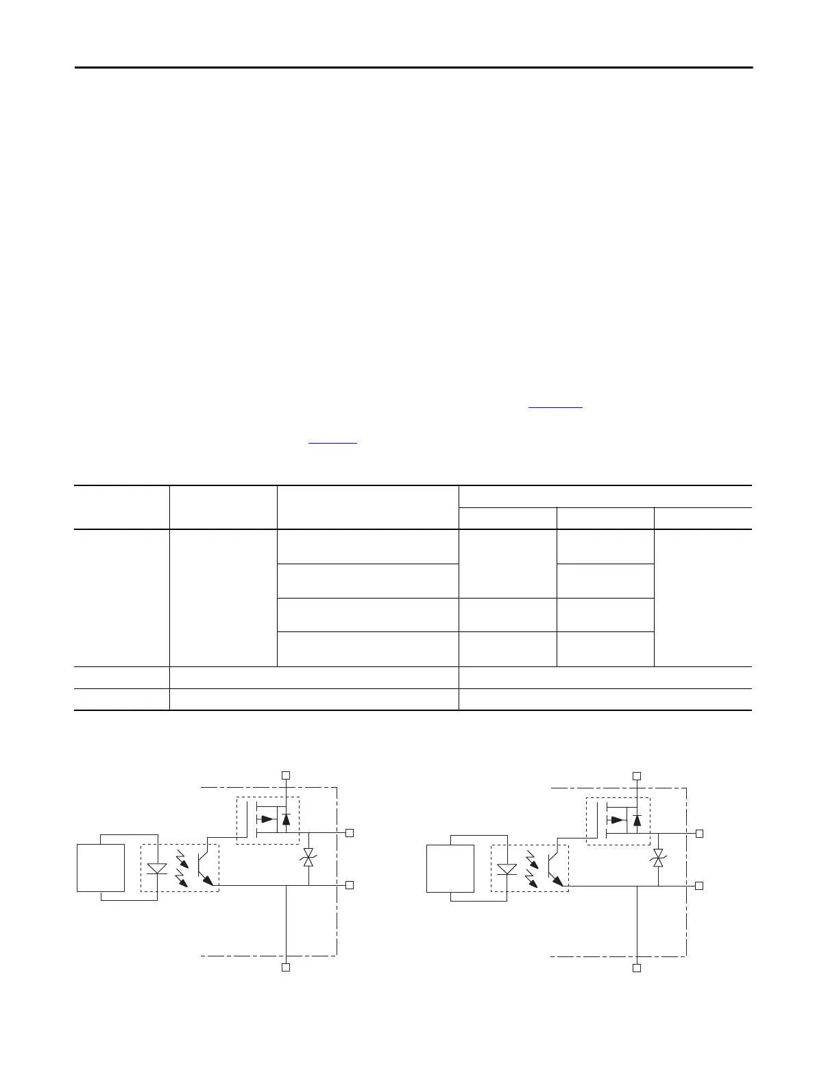
Motor/Resistive Brake Relay
The brake option is a spring-set holding brake that releases when voltage is
applied to the brake coil in the motor. The customer-supplied 24V power
supply drives the brake output through a solid-state relay (series C) and
mechanical relays (series A and B). The solid-state brake driver circuit provides
the following:
• Brake current-overload protection
• Brake over-voltage protection
Two connections are required for the (customer-supplied) motor/resistive
brake input power (BC-3 and BC-4) and two connections each for the motor
and resistive brake output, as shown in Figure 33
. Wiring is consistent with all
series releases. Connections are rated for +24V and current as shown in
Table 42
.
Table 42 - Brake Relay Output Specifications
Figure 33 - Brake Relay Circuit (series C)
(1) Noise suppression device.
Attribute Description IAM/AM Module
Brake Current Value, max
Series A Series B Series C
On-state current
(1)
Current flow when the
relay is closed
2094-AC05-Mxx,-x 2094-AC09-M02-x,
2094-AMP5-x, 2094-AM01-x, 2094-AM02-x
1.0 A
N/A
3.0 A
2094-BC01-Mxx-x, 2094-BC02-M02-x,
2094-BMP5-x, 2094-BM01-x, 2094-BM02-x
3.0 A
2094-AC16-M03-x, 2094-AC32-M05-x,
2094-AM03-x, 2094-AM05-x
1.3 A N/A
2094-BC04-M03-x, 2094-BC07-M05-x,
2094-BM03-x, 2094-BM05-x
3.0 A 3.0 A
On-state resistance Contact resistance when the relay is closed 1 Ω
Off-state voltage Voltage across the contacts when the relay is open 30V
(1) For motors requiring more than the maximum current specified, a relay must be added.
24V PWR (BC-3)
FQB22P10
MBRK+ (BC-5)
MBRK– (BC-6)
(1)
DBRK+ (BC-1)
DBRK– (BC-2)
24V COM (BC-4)
24V PWR (BC-3)
FQB22P10
(1)
24V COM (BC-4)
Resistive Brake Module Circuitry
Kinetix 6000
IAM/AM Module
Motor Brake Circuitry
Kinetix 6000
IAM/AM Module
Control
Board
Control
Board

 Loading...


