Publication 1763-UM001E-EN-P - June 2015
158 Specifications
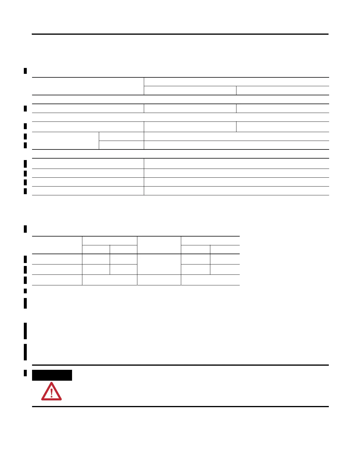
Output Specifications For Ordinary (Non-Hazardous) Locations only - General
Description 1763-
L16AWA, L16BWA, L16DWD L16BBB
Relay and FET Outputs
Maximum controlled load 1440 VA 720 VA
Maximum continuous current
Current per group common
5 A
(1)
5 A
Current per controller at 150V max 30 A or total of per-point loads, whichever is less
at 240V max 20 A or total of per-point loads, whichever is less
Relay Outputs
Turn on time/Turn off time
10 ms (max.)
(2)
Relay life - Electrical (Resistive Load) Refer to Relay Life Chart
Relay life - Mechanical 10,000,000 cycles
Load current 10 mA (.)
(1) 3.0 A above 40 °C
(2) scan time dependent.
Relay Contact Ratings
(1)
Maximum Volts Amperes Amperes
Continuous
Volt-Amperes
Make Break Make Break
240V AC
(2)
15.0 A 1.5 A
5.0 A
(3)
3600 VA 360 VA
120V AC
(4)
30.0 A 3.0 A 3600 VA 360 VA
125V DC
(5)
0.22 A 1.0 A 28 VA
(1) Pilot Duty Rating: (ordinary location) – B300, R150. (hazardous location) – C300, R150.
(2) For AC voltage applications lower than 240V AC but higher than 120V AC, the maximum make and break ratings are to
be obtained by dividing the volt-amperes rating by the application voltage.
(3) 3.0 A above 40 °C.
(4) For AC voltage applications lower than 120V AC, the maximum make current is to be the same as for 120V AC, and the
maximum break current is to be obtained by dividing the break volt-amperes rating by the application voltage, but the
currents are not to exceed the thermal continuous current.
(5) For DC voltage applications lower than 125V DC, the make/break ampere rating for relay contacts can be determined
by dividing the volt-ampere rating by the applied DC voltage but the current values are not to exceed the thermal
continuous current.
Do not exceed the “Current per group common” specification.

 Loading...


