Publication 1763-UM001E-EN-P - June 2015
Specifications 159
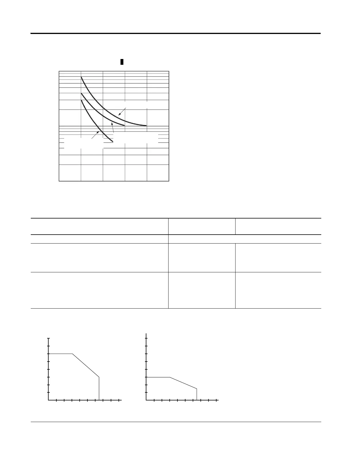
Number of operations (x 10
3
)
Switching capacity(A)
1000
10
0
500
300
100
50
30
2468 10
30 VDC resistive
load
250 VAC resistive load
250 VAC induction
load (cosφ=0.4)
BBB FET Output Specifications
Description General Operation
High Speed Operation
(1)
(Output 2 and 3 Only)
Power supply voltage 24V DC ( -15%, +10%)
On-state voltage drop:
•at maximum load current
•at maximum surge current
•1V DC
•2.5V DC
•Not Applicable
•Not Applicable
Current rating per point
•maximum load
•minimum load
•maximum leakage
•See graphs below.
•1.0 mA
•1.0 mA
•100 mA
•10 mA
•1.0 mA
Maximum output current (temperature dependent):
0.25
10˚C
(50˚F)
30˚C
(86˚F)
50˚C
(122˚F)
0.75A, 65˚C (149˚F)
1.5A, 30˚C (86˚F)
70˚C
(158˚F)
80˚C
(176˚F)
0.5
0.75
1.0
1.25
1.5
1.75
2.0
FET Current per Point
(1763-L16BBB)
Current (Amps)
Temperature
Valid
Range
1.0
10˚C
(50˚F)
30˚C
(86˚F)
50˚C
(122˚F)
1.5A, 65˚C (149˚F)
3.0A, 30˚C (86˚F)
70˚C
(158˚F)
80˚C
(176˚F)
2.0
3.0
4.0
5.0
6.0
7.0
8.0
FET Total Current
(1763-L16BBB)
Current (Amps)
Temperature
Valid
Range

 Loading...


