EasyManuals Logo
Home>Allen-Bradley>Touch terminals>PanelView Plus 1000

Allen-Bradley PanelView Plus 1000 User Manual

Allen-Bradley PanelView Plus 1000
132 pages
To Next Page IconTo Next Page
To Previous Page IconTo Previous Page
Page #81 background imageLoading...
Page #81 background image
Publication 2711P-UM001A-EN-P
Installing and Replacing Components 5-7
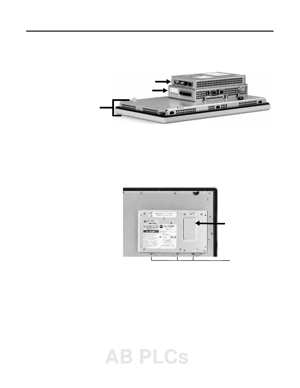
Replacing the Display
Module
This sections shows how to replace the Display Module
(2711P-RDxxxx). It is necessary to remove the Communication
Module from the Logic Module to perform this operation.
1. Disconnect power from the terminal.
2. Remove terminal from panel.
3. Detach the Communication Module (if attached) from the Logic
Module by removing the 4 screws.
4. Loosen the 6 captive screws that attach the Logic Module to the
Display Module.
5. Carefully lift the Logic Module from the terminal.
6. Set the Display Module aside.
Communication Module
Display
Module
Logic Module
Logic Module
Captive screws
on top and bottom
AB PLCs

Table of Contents

Other manuals for Allen-Bradley PanelView Plus 1000

Questions and Answers:

Question and Answer IconNeed help?

Do you have a question about the Allen-Bradley PanelView Plus 1000 and is the answer not in the manual?

Allen-Bradley PanelView Plus 1000 Specifications

General IconGeneral
BrandAllen-Bradley
ModelPanelView Plus 1000
CategoryTouch terminals
LanguageEnglish

Related product manuals