4-10 Troubleshooting
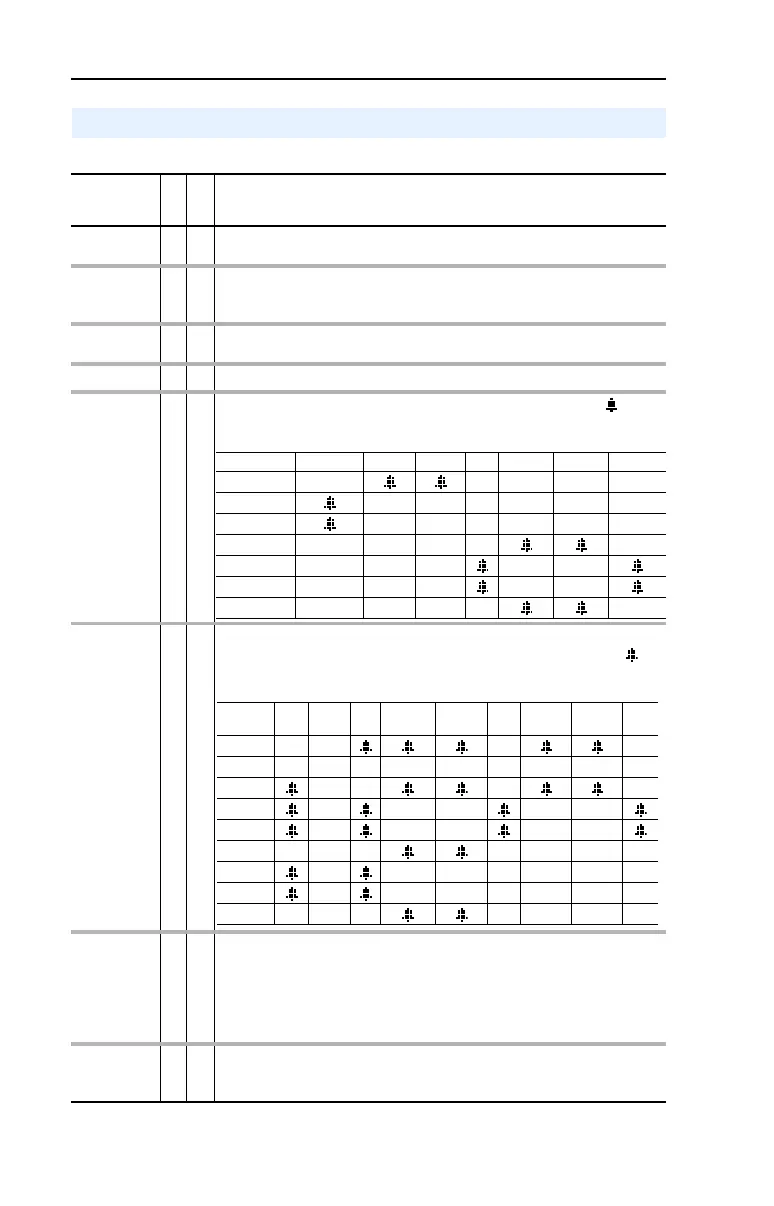
Table 4.C Alarm Descriptions and Actions
Alarm Descriptions
Alarm
No.
Type
(1)
Description
Analog In
Loss
5
➀
An analog input is configured for “Alarm” on signal loss and signal loss has
occurred.
Bipolar
Conflict
20
➁
Parameter 190 [Direction Mode] is set to “Bipolar” or “Reverse Dis” and one
or more of the following digital input functions is configured: “Fwd/Reverse,”
“Run Forward,” “Run Reverse,” “Jog Forward” or “Jog Reverse.”
Brake Slipped 32
➁
Encoder movement has exceeded the level in [BrkSlipCount] after the brake
was set.
Decel Inhibt 10
➀
Drive is being inhibited from decelerating.
Dig In
ConflictA
17
➁
Digital input functions are in conflict. Combinations marked with a “ ” will
cause an alarm.
Dig In
ConflictB
18
➁
A digital Start input has been configured without a Stop input or other
functions are in conflict. Combinations that conflict are marked with a “ ”
and will cause an alarm.
Dig In
ConflictC
19
➁
More than one physical input has been configured to the same input function.
Multiple configurations are not allowed for the following input functions.
Forward/Reverse Run Reverse Bus Regulation Mode B
Speed Select 1 Jog Forward Acc2 / Dec2
Speed Select 2 Jog Reverse Accel 2
Speed Select 3 Run Decel 2
Run Forward Stop Mode B
Drive OL
Level 1
8
➀
The calculated IGBT temperature requires a reduction in PWM frequency. If
[Drive OL Mode] is disabled and the load is not reduced, an overload fault will
eventually occur.
* Jog 1 and Jog 2 with Vector Control Option
Acc2/Dec2 Accel 2 Decel 2 Jog * Jog Fwd Jog Rev Fwd/Rev
Acc2 / Dec2
Accel 2
Decel 2
Jog*
Jog Fwd
Jog Rev
Fwd/Rev
* Jog 1 and Jog 2 with Vector Control Option
Start
Stop-
CF Run Run Fwd Run Rev Jog * Jog Fwd Jog Rev
Fwd/
Rev
Start
Stop-CF
Run
Run Fwd
Run Rev
Jog*
Jog Fwd
Jog Rev
Fwd/Rev

 Loading...


