1-4 Installation/Wiring
The drive Safety Ground - PE must be connected to system ground.
Ground impedance must conform to the requirements of national and
local industrial safety regulations and/or electrical codes. The integrity
of all ground connections should be periodically checked.
For installations within a cabinet, a single safety ground point or ground
bus bar connected directly to building steel should be used. All circuits
including the AC input ground conductor should be grounded
independently and directly to this point/bar.
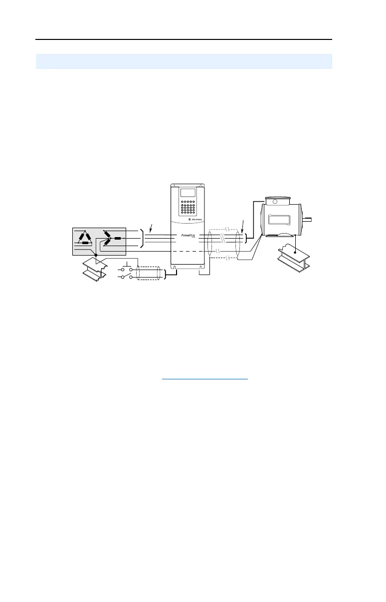
Figure 1.1 Typical Grounding
Safety Ground - PE
This is the safety ground for the drive that is required by code. This point
must be connected to adjacent building steel (girder, joist), a floor
ground rod or bus bar (see above). Grounding points must comply with
national and local industrial safety regulations and/or electrical codes.
Shield Termination - SHLD
The Shield terminal (see Figure 1.3 on page 1-10) provides a grounding
point for the motor cable shield. The motor cable shield should be
connected to this terminal on the drive (drive end) and the motor frame
(motor end). A shield terminating cable gland may also be used.
When shielded cable is used for control and signal wiring, the shield
should be grounded at the source end only, not at the drive end.
RFI Filter Grounding
Using an optional RFI filter may result in relatively high ground leakage
currents. Therefore, the filter must only be used in installations with
grounded AC supply systems and be permanently installed and
solidly grounded (bonded) to the building power distribution ground.
Ensure that the incoming supply neutral is solidly connected (bonded) to
the same building power distribution ground. Grounding must not rely
on flexible cables and should not include any form of plug or socket that
would permit inadvertent disconnection. Some local codes may require
redundant ground connections. The integrity of all connections should be
periodically checked. Refer to the instructions supplied with the filter.
General Grounding Requirements
U (T1)
V (T2)
W (T3)
R (L1)
S (L2)
T (L3)
PE
SHLD

 Loading...


