Chapter 1
Installation/Wiring
This chapter provides information on mounting and wiring the
PowerFlex 700 Drive.
Most start-up difficulties are the result of incorrect wiring. Every
precaution must be taken to assure that the wiring is done as instructed.
All items must be read and understood before the actual installation
begins.
For information on . . See page For information on. . See page
Opening the Cover
1-1 Disconnecting MOVs and
Common Mode Capacitors
1-13
Mounting Considerations 1-2
AC Supply Source Considerations 1-2 I/O Wiring 1-15
General Grounding Requirements 1-4 Reference Control 1-22
Fuses and Circuit Breakers 1-5 Auto/Manual Examples 1-23
Power Wiring 1-5 Lifting/Torque Proving 1-24
EMC Instructions 1-25
!
ATTENTION: The following information is merely a guide for proper
installation. The Allen-Bradley Company cannot assume responsibility
for the compliance or the noncompliance to any code, national, local or
otherwise for the proper installation of this drive or associated
equipment. A hazard of personal injury and/or equipment damage
exists if codes are ignored during installation.
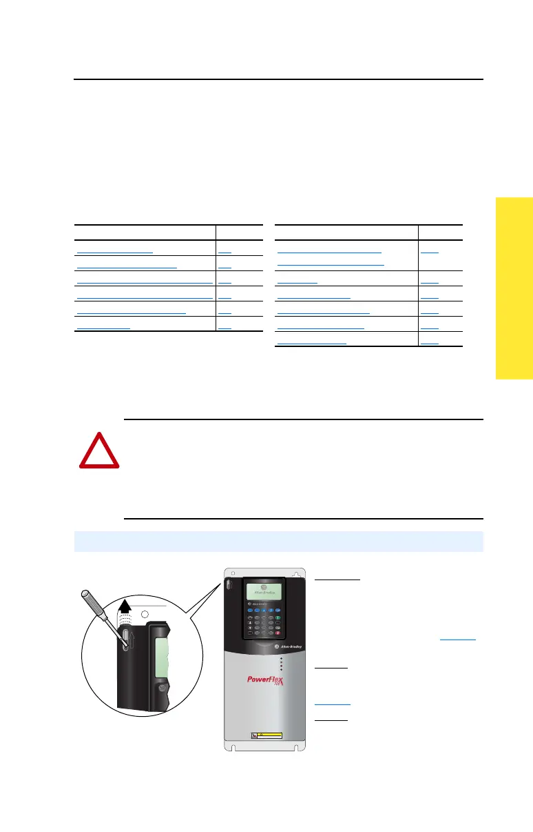
Opening the Cover
Esc
7 8 9
4 5 6
1 2 3
.
0 +/-
Sel
Jog
Alt
POWER
STS
PORT
MOD
NET A
NET B
Exp
Param #
S
.M
.A
.R
.T
.
E
x
it
L
a
n
g
A
u
t
o
/ M
a
n
R
e
m
o
v
e
HOT surfaces can cause severe burns
CAUTION
Frames 0-4
Locate the slot in the upper left corner.
Slide the locking tab up and swing the
cover open. Special hinges allow cover to
move away from drive and lay on top of
adjacent drive (if present). See page 1-7
for frame 4 access panel removal.
Frame 5
Slide the locking tab up, loosen the
right-hand cover screw and remove. See
page 1-7
for access panel removal.
Frame 6
Loosen 2 screws at bottom of drive cover.
Carefully slide bottom cover down & out.
Loosen the 2 screws at top of cover and
remove.

 Loading...


