C-12 Application Notes
When AC input power is lost, energy is being supplied to the motor from
the DC bus capacitors. The energy from the capacitors is not being
replaced (via the AC line), thus, the DC bus voltage will fall rapidly. The
drive must detect this fall and react according to the way it is
programmed. Two parameters display DC bus voltage:
• [DC Bus Voltage] - displays the instantaneous value
• [DC Bus Memory] - displays a 6 minute running average of the
voltage.
All drive reactions to power loss are based on [DC Bus Memory]. This
averages low and high line conditions and sets the drive to react to the
average rather than assumed values. For example, a 480V installation
would have a 480V AC line and produce a nominal 648V DC bus. If the
drive were to react to a fixed voltage for line loss detect, (i.e. 533V DC),
then normal operation would occur for nominal line installations.
However, if a lower nominal line voltage of 440V AC was used, then
nominal DC bus voltage would be only 594V DC. If the drive were to
react to the fixed 533V level (only –10%) for line loss detect, any
anomaly might trigger a false line loss detection. Line loss, therefore
always uses the 6 minute average for DC bus voltage and detects line
loss based on a fixed percentage of that memory. In the same example,
the average would be 594V DC instead of 650V DC and the fixed
percentage, 27% for “Coast to Stop” and 18% for all others, would allow
identical operation regardless of line voltage.
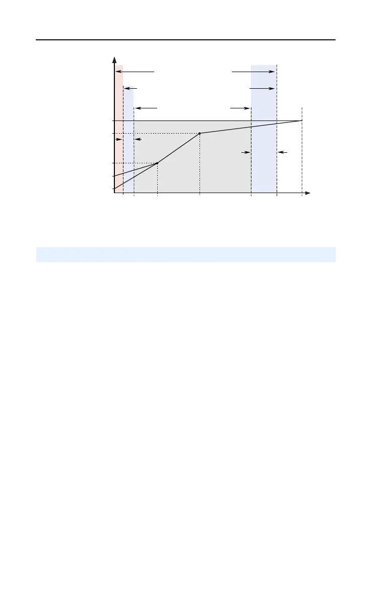
Frequency
Output Voltage
Note 1: The lower limit on this range can be 0 depending on the value of Speed Adder
Overspeed
Limit
Frequency Trim
due to Speed
Control Mode
Maximum
Voltage
Motor NP
Voltage
Run
Boost
Break
Voltage
Start
Boost
Allowable Output Frequency Range - Normal Operation
1
Allowable Speed Reference Range
Allowable Output Frequency Range -
Bus Regulation or Current Limit
Maximum
Frequency
Motor NP Hz0 Break
Frequency
Maximum
Speed
Minimum
Speed
Output
Frequency
Limit
Power Loss Ride Through

 Loading...


