EasyManuals Logo
Home>Allen-Bradley>Controller>powerflex 700

Allen-Bradley powerflex 700 User Manual

Allen-Bradley powerflex 700
198 pages
To Next Page IconTo Next Page
To Previous Page IconTo Previous Page
Page #157 background imageLoading...
Page #157 background image
Appendix C
Application Notes
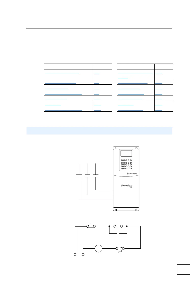
Figure C.1 External Brake Resistor Circuitry
For information on . . See page . . For information on . . See page . .
External Brake Resistor
C-1 Process PI for Standard
Control
C-13
Lifting/Torque Proving C-2 Reverse Speed Limit C-16
Minimum Speed C-7 Skip Frequency C-17
Motor Control Technology C-8 Sleep Wake Mode C-19
Motor Overload C-10 Start At PowerUp C-21
Overspeed C-11 Stop Mode C-22
Power Loss Ride Through C-12 Voltage Tolerance C-24
External Brake Resistor
Power On
R (L1)
S (L2)
T (L3)
Power Source DB Resistor Thermostat
Power Off
M
M
(Input Contactor) M
Three-Phase
AC Input

Table of Contents

Other manuals for Allen-Bradley powerflex 700

Questions and Answers:

Question and Answer IconNeed help?

Do you have a question about the Allen-Bradley powerflex 700 and is the answer not in the manual?

Allen-Bradley powerflex 700 Specifications

General IconGeneral
BrandAllen-Bradley
Modelpowerflex 700
CategoryController
LanguageEnglish

Related product manuals