Application Notes C-13
The PowerFlex 70 uses only these fixed percentages. The PowerFlex 700
can selectively use the same percentages or the user can set a trigger
point for line loss detect. The adjustable trigger level is set using [Power
Loss Level] (see [Power Loss Level]
on page 3-38).
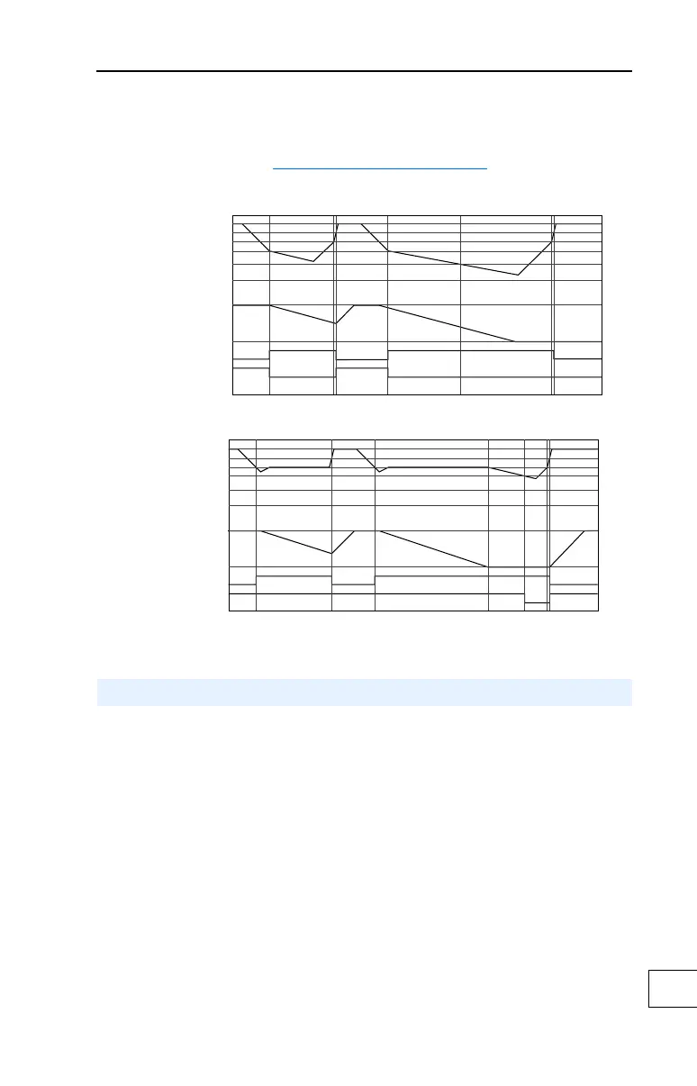
Figure C.4 Power Loss Mode = Coast
Figure C.5 Power Loss Mode = Decel
The internal PI function of the PowerFlex 700 provides closed loop
process control with proportional and integral control action. The
function is designed for use in applications that require simple control of
a process without external control devices. The PI function allows the
microprocessor of the drive to follow a single process control loop.
The PI function reads a process variable input to the drive and compares
it to a desired setpoint stored in the drive. The algorithm will then adjust
the output of the PI regulator, changing drive output frequency to try and
make the process variable equal the setpoint.
Nominal
73%
Bus Voltage
Motor Speed
Output Enable
Power Loss
Nominal
82%
Bus Voltage
Motor Speed
Output Enable
Power Loss
Process PI for Standard Control

 Loading...


