1 Publication 1764-UM001A-US-P
Chapter
3
Installing and Wiring Your Module
After reading this chapter, you should be able to:
• set the module’s jumpers
• install your module into your SLC 500 fixed or modular controller system
• wire the mating connectors of the cables used to interface user devices to the
module ports
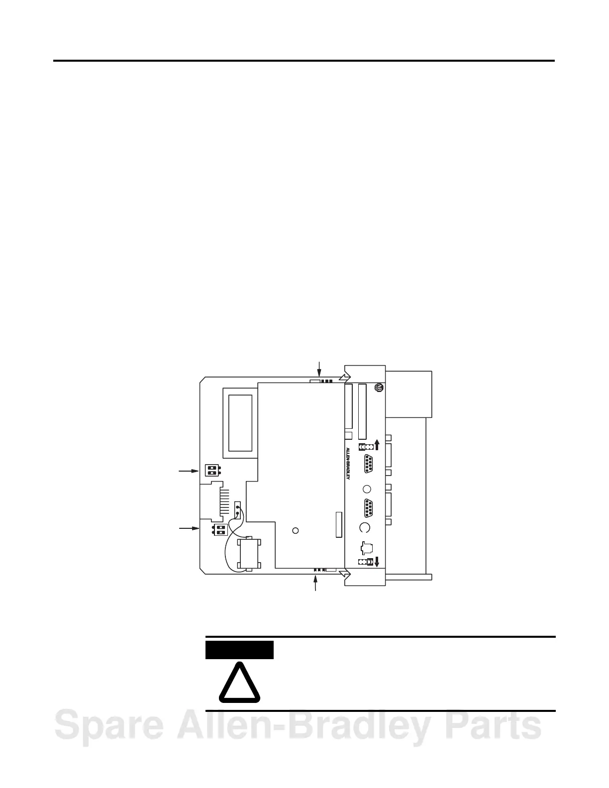
Setting Module Jumpers
The module has four sets of jumpers that you need to set. Jumpers JW1 and JW2
configure ports PRT1 and PRT2. Jumper JW3 configures the type of optional
memory module. Jumper JW4 configures the program port. Figure 3.1 shows the
location of these jumpers.
Figure 3.1 Jumper Locations
SLC 500
BASIC MODULE
CAT SER
SERIAL NO. FRN
JW1
12345
6789
U
L
PRT1
123
45
6789
PRT2
SA
JW2
DH485
JW3
JW4
JW1
JW2
ATTENTION
Do not expose the module to surfaces or other areas that may
typically hold an electrostatic charge. Electrostatic charges can
alter or destroy memory.
Spare Allen-Bradley Parts

 Loading...


