Publication 1746-UM004A-US-P
B-3
Optional Memory
Module Selection
(Jumper JW3)
See Figure 3.1 on page 3-1 for the locations of the four jumpers.
See Figure 3.4 on page 3-4 for jumper JW3 pin assignments and settings.
Specify the optional memory module selection for the system by filling in the table
below.
What to Do Next: Give a copy of this worksheet to the hardware installer. Store
this worksheet with your application program for future reference.
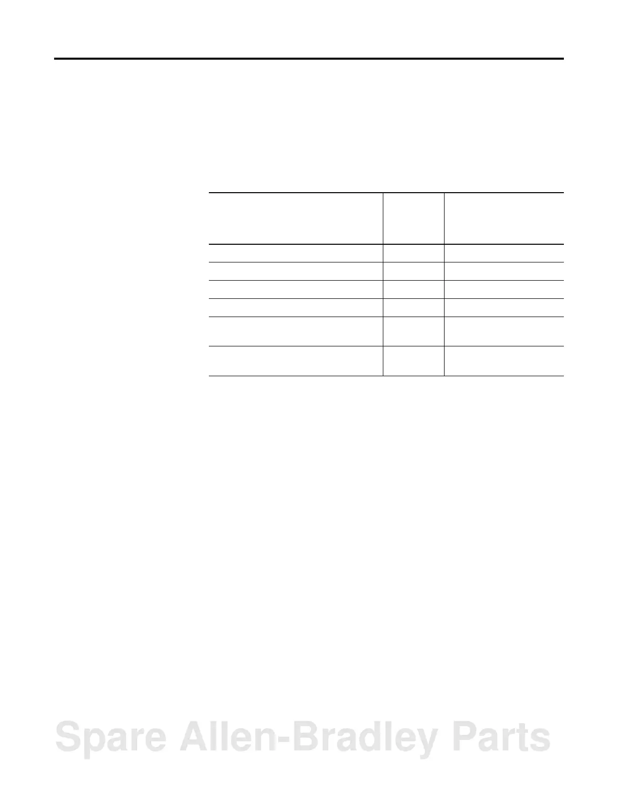
Table B.3 Optional Memory Module Selection
Memory Module Option Optional
Memory
Module
Selection
Corresponding Jumper
Position on JW3
1747-M1 8K byte EEPROM (1746-BAS only) Across pins 1 and 3, 2 and 4
1747-M2 32K byte EEPROM (1746-BAS only) Across pins 1 and 3, 2 and 4
1747-M3 8K byte UVPROM (1746-BAS only) Across pins 1 and 3, 2 and 4
1747-M4 32K byte UVPROM (1746-BAS only) Across pins 3 and 5, 4 and 6
1771-DBMEM1 8K byte EEPROM
(1746-BAS-T only)
Across pins 1 and 3, 2 and 4
1771-DBMEM 32K byte EEPROM
(1746-BAS-T only)
Across pins 1 and 3, 2 and 4
Spare Allen-Bradley Parts

 Loading...


