1 Publication 176-UM04A-US-P
Appendix
A
Specifications
Module Hardware
Specifications
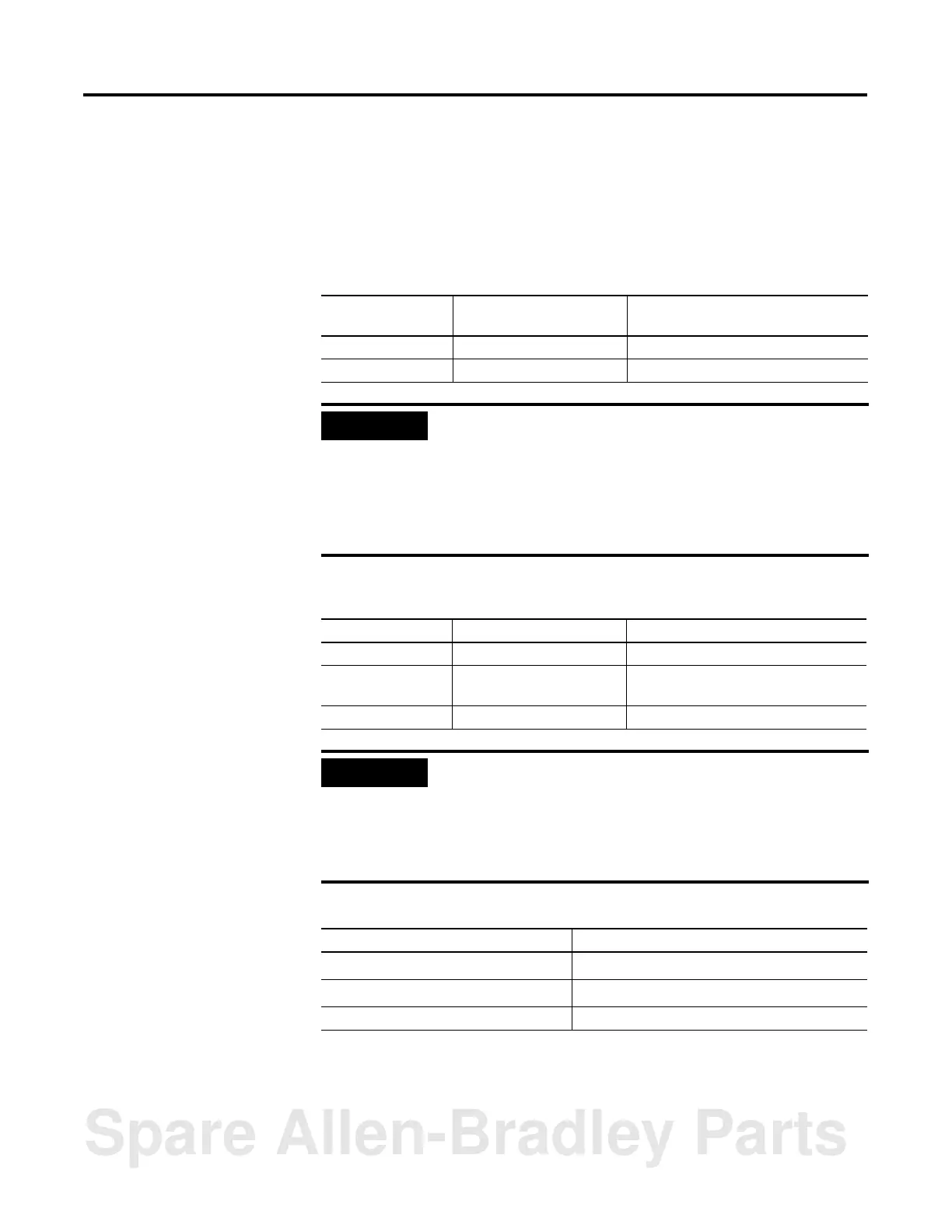
The module hardware specifications are listed in the following tables.
Table A.1 Power Consumption
Operating
Voltage
Current Requirement
Module Only
Current Requirement
Module With Link Coupler
5V dc .150 A .150 A
24V dc .040 A .125 A
IMPORTANT
If a Hand-Held Terminal, Data Table Access Module, or interface
converter is connected to the link coupler, the additional
backplane power draw of these components (shown in Table A.1)
must be added to the .125 Amperes listed in the table above.
This only applies when the module is connected to the network
via the link coupler and 1747-C10 Cable or 1747-C11 Cable.
This does not apply when the 1747-C13 Cable is used.
Table A.2 Power Consumption of Hand-Held Terminal, Data Table Access Module, and
Interface Converter
Component Operating Voltage Current Requirement
Hand-Held Terminal 24V dc .105A
Data Table Access
Module
24V dc .104A
Interface Converter 24V dc .060A
IMPORTANT
The BASIC module receives its power from the SLC backplane.
The power consumption of the module must be taken into
consideration when planning your SLC 500 system. Refer to the
documentation supplied with your SLC 500 fixed or modular
controller for additional information on power supplies and
current requirements.
Table A.3 Environmental Conditions
Condition Range
Operating temperature
0
°
C to 60
°
C (32
°
F to 140
°
F)
Storage temperature
-40
°
C to 85
°
C (-40
°
F to 185
°
F)
Relative humidity 5% to 95% (non-condensing)
Spare Allen-Bradley Parts

 Loading...


