Publication 1764-UM001A-US-P
Installing and Wiring Your Module 3-7
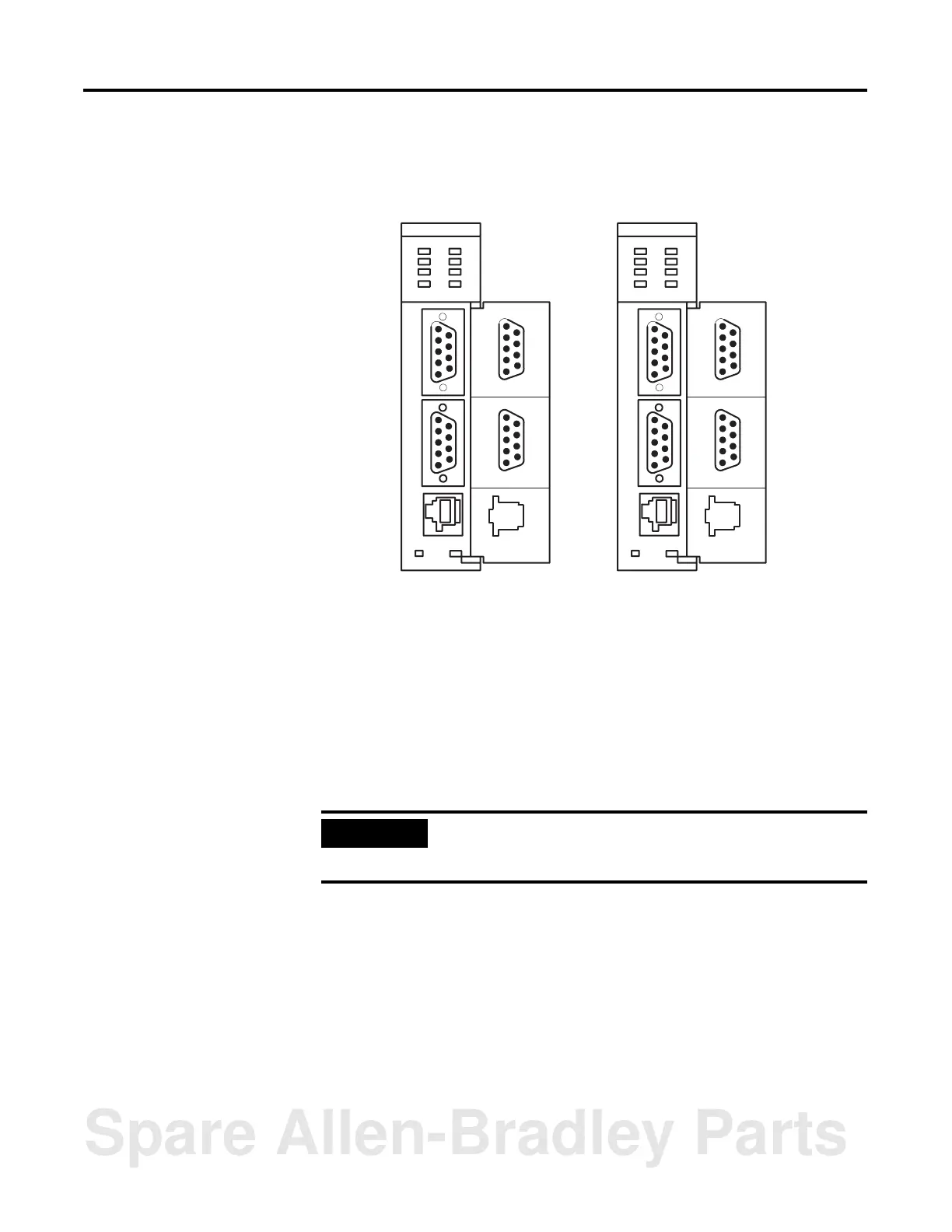
Wiring Your
Communication Ports
The locations of the module’s communication ports, PRT1, PRT2, and DH485,
are shown in Figure 3.7.
Figure 3.7 Communication Ports
Wiring to Ports PRT1
and PRT2
Ports PRT1 and PRT2 can communicate to user devices through RS-232/423,
RS-422, and RS-485 communication modes. Set jumpers JW1 and JW2 to reflect
the communication mode you desire. The table below lists the pin assignments for
ports PRT1 and PRT2.
Refer to the MODE command in the BASIC Language Reference Manual,
publication number 1746-RM001A-US-P, for the default programming port
configuration information
.
Use these pin assignments to wire the mating connector of the cable used to
interface a user device to port PRT1. The sockets of this connector must be wired
to correspond to the selected communication mode.
PR T1
5
4
3
2
1
9
8
7
6
PR T2
5
4
3
2
1
9
8
7
6
DH485
BASIC
PR T1
5
4
3
2
1
9
8
7
6
PR T2
5
4
3
2
1
9
8
7
6
DH485
BASIC-T
IMPORTANT
When default communications are selected via JW4, the module
defaults to the Command mode on powerup. Refer to page 3-4 of
this manual for the default communication settings.
Spare Allen-Bradley Parts

 Loading...


