Publication 1764-UM001A-US-P
3-10 Installing and Wiring Your Module
DCE - Data Communication Equipment
Devices such as modems are Data Communication Equipment (DCE). The
pinouts on these terminals are defined for ease of interfacing with DTE equipment.
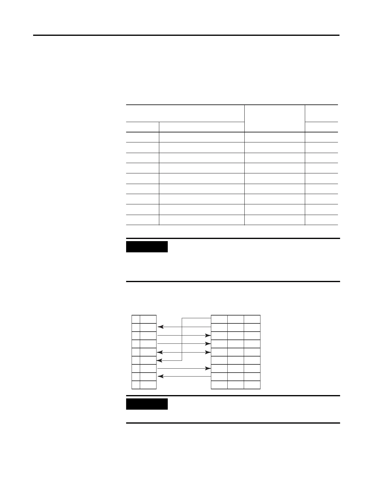
Figure 3.8 RS-232/423 Wiring Diagram - Module to a Modem (Hardware Handshaking
Enabled)
Table 3.3 DCE Configurations
DCE 9 pinout Signal from DCE
Perspective
DCE 25
pinout
Pin # Signal Description Pin #
1 CD-Carrier Detect Output 8
2 RXD-Received Data Output 3
3 TXD-Transmitted Data Input 2
4 DTR-Data Terminal Ready Input 20
5 Com-Signal Common Shared 7
6 DSR-Data Set Ready Output 6
7 RTS-Request to Send Input 4
8 CTS-Clear to Send Output 5
9 RI-Ring Indicator Output 22
IMPORTANT
All signal directions are listed in the previous two tables are valid.
For example, TXD, Transmitted Data, is a DTE output but is
also a DCE input. The signal description is the same for both the
DTE and DCE but the direction of the signal (perspective) has
changed based on whether you have a DTE or DCE device.
N.C.1
RXD2
TXD3
DTR4
COM5
DSR6
RTS7
CTS8
N.C.9
CD
RXD
TXD
DTR
COM
DSR
RTS
CTS
RI
8
3
2
20
7
6
4
5
22
1
2
3
4
5
6
7
8
9
Basic DTE DCE 9-pin 25-pin
IMPORTANT
For DCE devices other than modems, connect the DSR of the
module with the DSR of the device. The CD signal of the device
(other than a modem) is not used

 Loading...


