Publication 1747-UM011G-EN-P - June 2008
150 Troubleshooting
can then use a programmer/operator interface device to change the
processor mode.
Identifying SLC 5/03, SLC 5/04, and SLC 5/05 Processor Errors
The following status indicators and tables provide you with
information regarding error messages, possible cause(s) for the error,
and recommended action to resolve the error.
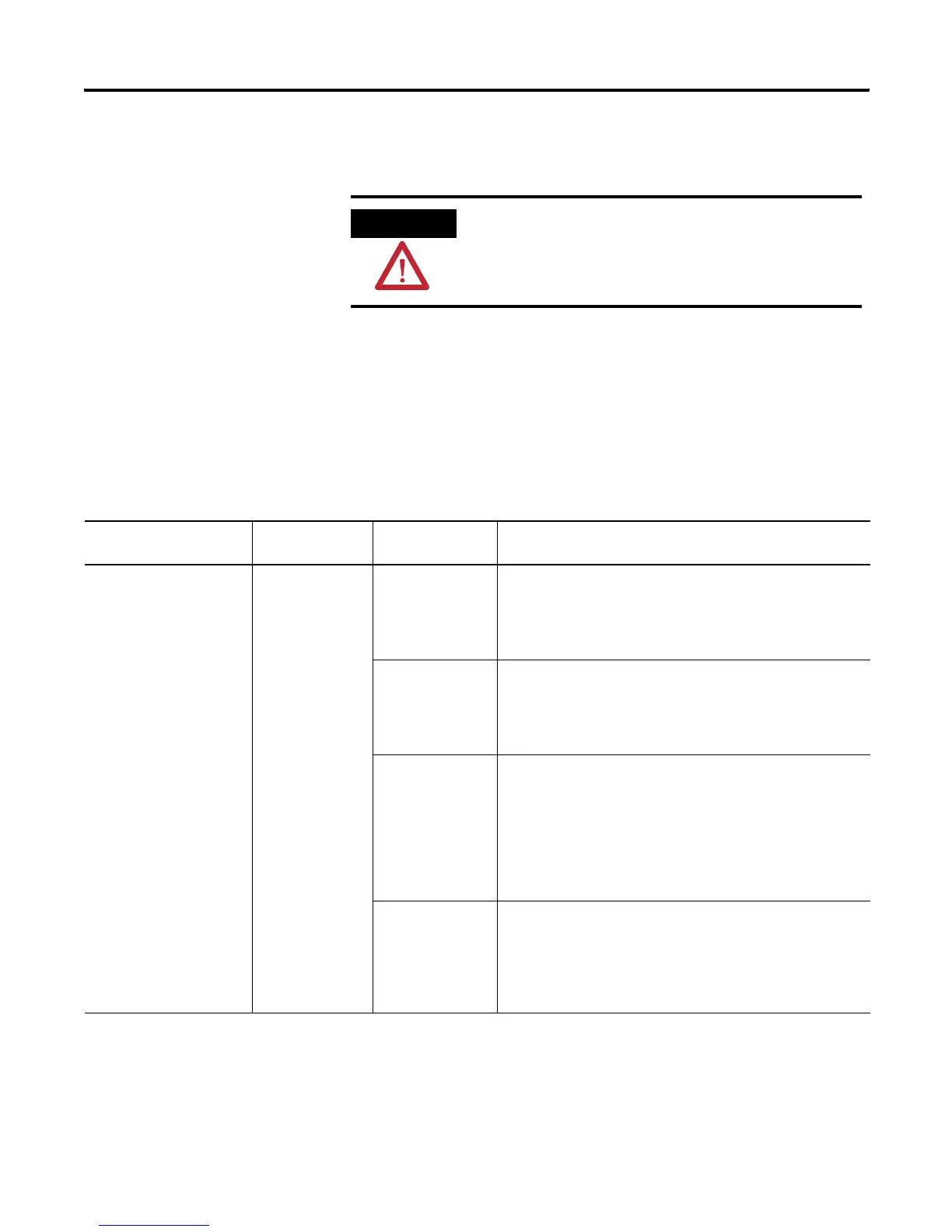
ATTENTION
If you clear a processor fault using the keyswitch, the
processor immediately enters the Run mode.
SLC 5/03, SLC 5/04, and SLC 5/05 Processor Errors
If the status indicators
indicate
The following
error exists
Probable Cause Recommended Action
• All status indicators are
off
• Status of any
Communication status
indicator does not
matter
Inadequate system
power
No line power. 1. Verify proper line voltage and connections on the power
terminals.
2. Verify proper 120/240V power supply jumper selection. See
page 106.
Power supply fuse
blown.
1. Check the incoming power fuse, check for proper incoming
power connections. Replace fuse.
2. If fuse blows again, replace the power supply.
See page 139 on fuse replacement.
Power supply
overload.
1. Remove line power to power supply. remove several output
modules from the chassis. wait five minutes. reapply power.
2. If condition reoccurs, re-calculate module configuration
power required and verify proper power supply selection.
See page 36. This problem can occur intermittently if power
supply is slightly overloaded when output loading and
temperature varies.
Defective power
supply.
1. Recheck other probable causes.
2. Monitor the line power to chassis power supply for possible
transient or shorting.
3. Replace the power supply.