Publication 1747-UM011G-EN-P - June 2008
Troubleshooting 165
Troubleshooting Your
Output Modules
The following will assist you in troubleshooting your output modules.
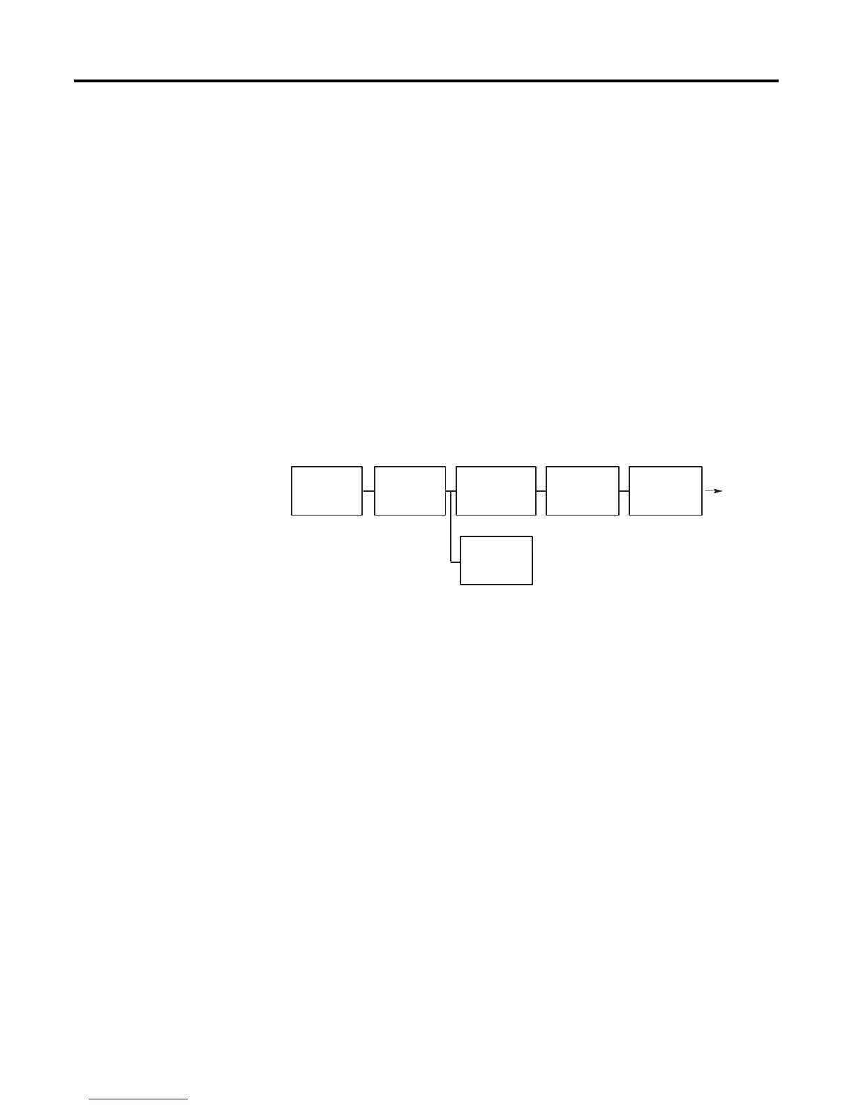
Output Circuit Operation
An output circuit controls the output signal in the following manner.
1. Logic circuits determine the output status.
2. An output status indicator indicates the status of the output
signal.
3. Opto-electrical isolation separates output circuit logic and
backplane circuits from field signals.
4. The output driver turns the corresponding output on or off.
Output
Output
Drivers
Opto-Electrical
Isolation
Logic
Circuits
Backplane
status indicator
Logic
Circuits

 Loading...


