Publication 1747-UM011G-EN-P - June 2008
Specifications 179
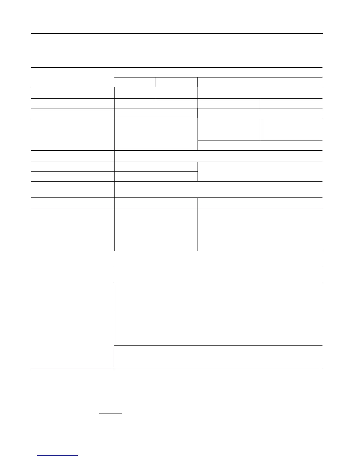
1746-P5, 1746-P6, and 1746-P7 Power Supplies
Attribute Value
1746-P5 1746-P6 1746-P7
Line voltage 90-146V dc 30-60V dc
10-30V dc
(5)
Typical line power requirement 85VA 100VA 12V dc input: 50VA 24V dc input: 75VA
Inrush current, max 20A 20 A (required for turn-on)
Internal current capacity 5 A at 5V dc
0.96 A at 24V dc
12V dc input:
2.0 A at 5V dc 0.46 A at 24V
dc
24V dc input:
3.6 A at 5V dc
0.87 A at 24V dc
See P7 current capacity chart
Fuse protection
(1)
Fuse is soldered in place
24V dc user-power current capacity 200 mA not applicable
24V dc user-power voltage range 18-30V dc
Ambient temperature, operating 0 °C...60 °C (32 °F...140 °F)
Current capacity is derated 5% above 55 °C (131°F)
Isolation
(2)
1800V ac RMS for 1 s 600V ac RMS for 1 s
CPU hold-up time
(3)
20 ms (full load)
3000 ms (no load)
5 ms (full load)
1500 ms (no load)
12V dc input:
1.37 ms at 0V dc (full load)
895 ms at 0V dc (no load)
10 ms at 9V dc (full load)
continuous at 9V dc (no
load)
24V dc input:
40 ms at 0V dc (full load)
1860 ms at 0V dc (no load)
790 ms at 11V dc (full load)
continuous at 11V dc (no
load)
Certification
(when product is marked)
UL Listed Industrial Control Equipment for Class I, Division 2, Groups A, B, C, D Hazardous
Locations
C-UL Listed Industrial Control Equipment for Class I, Division 2, Groups A, B, C, D Hazardous
Locations
CE
(4)
European Union 89/336/EEC EMC Directive, compliant with:
EN 50082-2 Industrial Immunity
EN 50081-2 Industrial Emissions
or
EN 61000-6-2 Industrial Immunity
EN 61000-6-4 Industrial Emissions
European Union 73/23/EEC LVD Directive, compliant with safety related portions of:
EN61131-2 Programmable Controllers
C-Tick
Australian Radio Communications Act, compliant with:
AS/NZS 2064 Industrial Emissions
(1)
Power supply fuse is intended to guard against fire hazard due to short-circuit conditions. This fuse may not protect the supply from miswiring or excessive transient in the
power line.
(2)
Isolation is between input terminals and backplane.
(3)
CPU hold-up time is for 0V unless specified. Hold-up time is dependent on power supply loading.
(4)
See the Product Certification link at http://ab.com for Declarations of Conformity, Certificates, and other certification details.
(5)
See page 70 for information on power supply under voltage operation.

 Loading...


