Publication 1747-UM011G-EN-P - June 2008
Calculating Heat Dissipation for the SLC 500 Control System 269
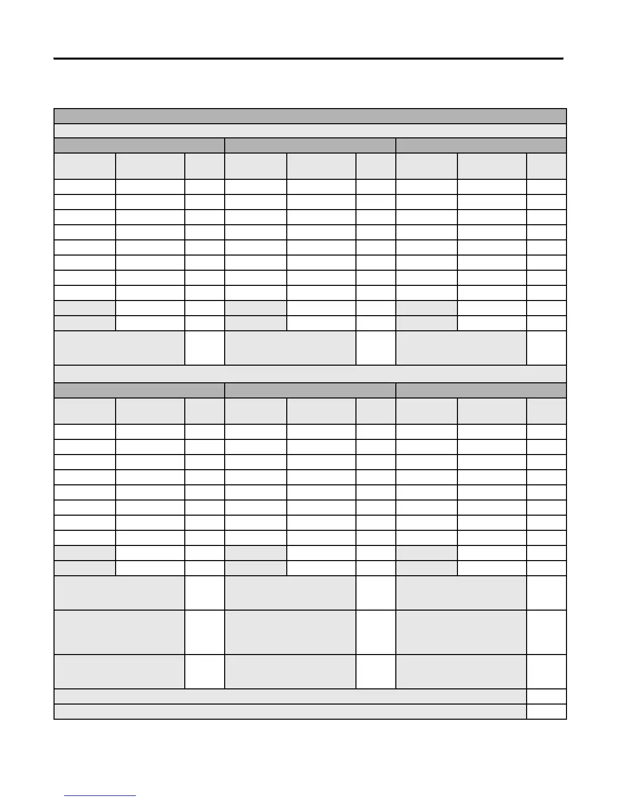
Blank Worksheet
Procedure for calculating the total heat dissipation for the controller
1. Write in the total watts dissipated by the processor, I/O, and speciality modules, and any peripheral devices attached to the processor.
Chassis Number 1 Chassis Number 2 Chassis Number 3
Slot Catalog No. Heat Dis
(Watts)
Slot Catalog No. Heat Dis
(Watts)
Slot Catalog No. Heat Dis
(Watts)
Peripheral Dev Peripheral Dev Peripheral Dev
Peripheral Dev Peripheral Dev Peripheral Dev
2.Add the heat dissipation values
together for your total chassis
heat dissipation.
2.Add the heat dissipation values
together for your total chassis
heat dissipation.
2.Add the heat dissipation values
together for your total chassis
heat dissipation.
3.Calculate the power supply loading for each chassis (minimum watts) for each device.
(1)
Chassis Number 1 Chassis Number 2 Chassis Number 3
Slot Catalog No. Heat Dis
(Watts)
Slot Catalog No. Heat Dis
(Watts)
Slot Catalog No. Heat Dis
(Watts)
User Power User Power User Power
Peripheral Dev Peripheral Dev Peripheral Dev
4.Add the heat dissipation values
together for your power supply
loading.
4.Add the heat dissipation values
together for your power supply
loading.
4.Add the heat dissipation values
together for your power supply
loading.
5.Use the power supply loading (step
4) for each chassis and the graphs
on page 266 to determine power
supply dissipation.
5.Use the power supply loading (step
4) for each chassis and the graphs
on page 266 to determine power
supply dissipation.
5.Use the power supply loading (step
4) for each chassis and the graphs
on page 266 to determine power
supply dissipation.
6.Add the chassis dissipation (step 2)
to the power supply dissipation
(step 5).
6.Add the chassis dissipation (step 2)
to the power supply dissipation
(step 5).
6.Add the chassis dissipation (step 2)
to the power supply dissipation
(step 5).
7.Add the values together from step 6 across to the right.
8.Covert the value from step 7 to BTUs/hr by multiplying the total heat dissipation of your controller by 3.414.
(1)
If you have a device connected to user power, multiply 24V dc by the amount of current used by that device. Include user power in the total power supply loading.

 Loading...


