227 Publication 1747-UM011G-EN-P - June 2008
Appendix
E
Power Supply Worksheet
Power Supply Loading
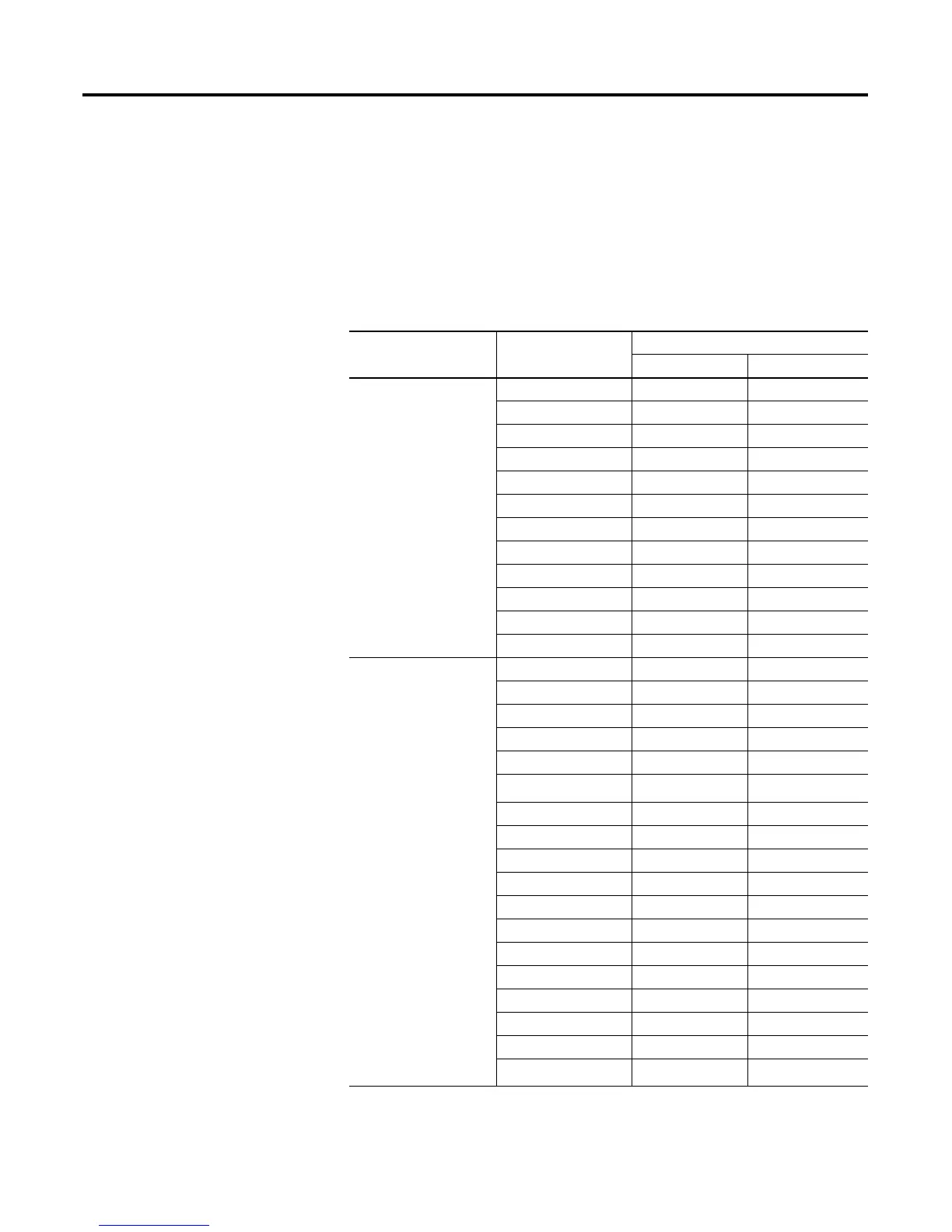
Use the table below to calculate the power supply loading for each
chassis in your SLC modular application.
Hardware Component Cat. No. Maximum Current (A)
at 5V dc at 24V dc
Processors 1747-L511 0.090 0
1747-L514 0.090 0
1747-L524 0.090 0
1747-L531 0.500 0.175
1747-L532 0.500 0.175
1747-L533 0.500 0.175
1747-L541 1.000 0
1747-L542 1.000 0
1747-L543 1.000 0
1747-L551 1.000 0
1747-L552 1.000 0
1747-L553 1.000 0
Digital Input Modules 1746-IA4 0.035 -
1746-IA8 0.050 -
1746-IA16 0.085 -
1746-IB8 0.050 -
1746-IB16 0.050 -
1746-IB32
(1)
0.050 -
1746-IC16 0.050 -
1746-IG16 0.140 -
1746-IH16 0.085 -
1746-IM4 0.035 -
1746-IM8 0.050 -
1746-IM16 0.085 -
1746-IN16 0.085 -
1746-ITB16 0.050 -
1746-ITV16 0.085 -
1746-IV8 0.050 -
1746-IV16 0.085 -
1746-IV32
(1)
0.050 -

 Loading...


