Publication 1747-UM011G-EN-P - June 2008
230 Power Supply Worksheet
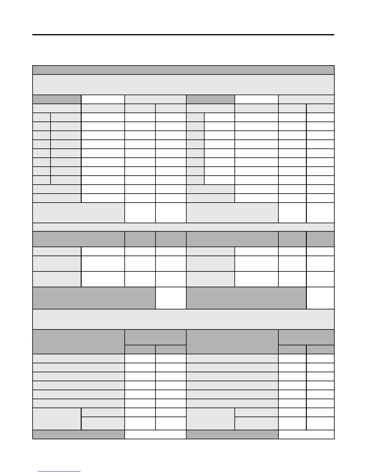
Blank Worksheet
Procedure
1. For each slot of the chassis that contains a module, list the slot number, the catalog number of the module, and its 5V and 24V maximum currents. Also
include the power consumption of any peripheral devices that may be connected to the processor other than a 1747-DTAM or 1747-PIC interface-the
power consumption of these devices is accounted for in the power consumption of the processor.
Chassis Number Maximum Currents Chassis Number Maximum Currents
Slot Number Cat. No. at 5V dc at 24V dc Slot Number Cat. No. at 5V dc at 24V dc
Slot Slot
Slot Slot
Slot Slot
Slot Slot
Slot Slot
Slot Slot
Slot Slot
Slot Slot
Peripheral Device Peripheral Device
Peripheral Device Peripheral Device
2.Add the loading currents of all the system
devices at 5 and 24V dc to determine the
Total Current.
2.Add the loading currents of all the system
devices at 5 and 24V dc to determine the
Total Current.
3.For 1746-P4 power supplies, calculate the total power consumption of all system devices. If you are not using a 1746-P4 power supply, go to step 4.
Current Multiply by = Watts Current Multiply
by
= Watts
Total Current at 5V dc 5V Total Current at 5V dc 5V
Total Current
at 24V dc
24V Total Current
at 24V dc
24V
User Current
at 24V dc
24V User Current
at 24V dc
24V
Add the Watts values to determine Total Power
(cannot exceed 70 Watts)
Add the Watts values to determine Total Power
(cannot exceed 70 Watts)
4.Choose the power supply from the list of catalog numbers shown below. Compare the Total Current required for the chassis with the Internal Current
capacity of the power supplies. Be sure that the Total Current consumption for the chassis is less than the Internal Current Capacity for the power
supply, for both 5V and 24V loads.
Cat. No. Internal Current
Capacity
Cat. No. Internal Current
Capacity
at 5V dc at 24V dc at 5V dc at 24V dc
1746-P1 2.0A 0.46A 1746-P1 2.0A 0.46A
1746-P2 5.0A 0.96A 1746-P2 5.0A 0.96A
1746-P3 3.6A 0.87A 1746-P3 3.6A 0.87A
1746-P4 (see step 3) 10.0A 2.88A 1746-P4 (see step 3) 10.0A 2.88A
1746-P5 5.0A 0.96A 1746-P5 5.0A 0.96A
1746-P6 5.0A 0.96A 1746-P6 5.0A 0.96A
1746-P7 (See
page 37 for current
capacity.)
12V Input 2.0A 0.46A 1746-P7 (See
page 37 for current
capacity.)
12V Input 2.0A 0.46A
24V Input 3.6A 0.87A 24V Input 3.6A 0.87A
Required Power Supply Required Power Supply

 Loading...


