Publication 1747-UM011G-EN-P - June 2008
System Installation Recommendations 61
Grounding Guidelines
In solid-state control systems, grounding helps limit the effects of electrical
noise due to electromagnetic interference (EMI). The ground path for the SLC
500 controller and its enclosure is provided by the equipment grounding
conductor.
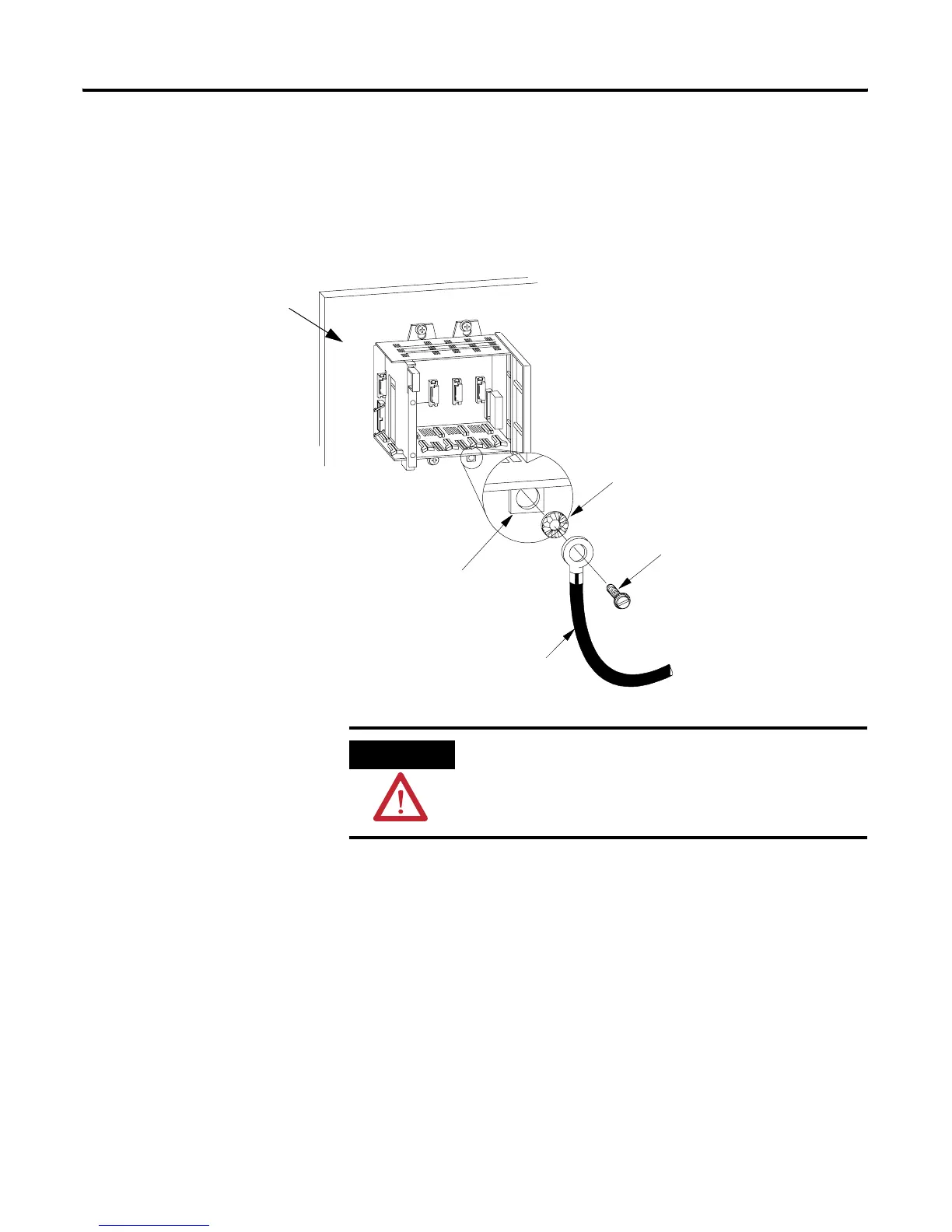
Connect Equipment Grounding Conductor to Ground Bus
Ground connections should run from the chassis and power supply on each
SLC 500 controller and expansion unit to the ground bus. Exact connections
will differ between applications.
Size M4 or M5 (#10 or #12) Internal
Star Washer
Metal Panel
(Must be connected
to earth ground.)
Scrape paint off panel to insure
electrical connection between
chassis and grounded metal panel.
Chassis
Mounting Tab
4M or 5M (#10 or #12 phillips
screw
5.2 mm
2
(10 AWG) to
Ground Bus
ATTENTION
The 1746 chassis, the enclosure, and other control devices must
be properly grounded. All applicable codes and ordinances must
be observed when wiring the SLC 500 controller system.

 Loading...


