Publication 1747-UM011G-EN-P - June 2008
Quick Start for Experienced Users 17
2. Install the chassis. Reference
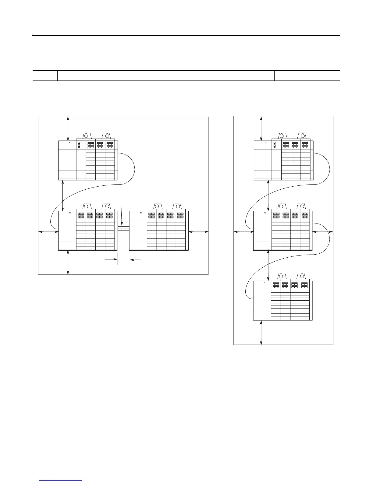
1. Determine the amount of spacing required for mounting your system.
Chapter 3
(System Installation
Recommendations)
C
1746-C9 Cable
SLC 500 Controller
1746-C7 Cable
D
SLC 500 Controller
SLC 500 Controller
B
C
A
B
C
A
B
B
SLC 500 Controller
SLC 500 Controller
SLC 500 Controller
A
1746-C9
Cable
1746-C9
Cable
C
Recommended Spacing
A. 15.3...20.0 cm (6...8 in.) when using the 1746-C9 cable. If you mount two 13-slot
chassis above each other, the distance cannot exceed 10.2...12.7 cm (4...5 in.).
B. Greater than 10.2 cm (4 in.).
C. Greater than 15.3 cm (6 in.).
D. 6.35...10.2 cm (2.5...4 in.) when using the 1746-C7 cable. If you are using a 1746-P4
power supply, your maximum spacing is 6.35 cm (2.5 in.).
B

 Loading...


