Publication 1747-UM011G-EN-P - June 2008
52 Selecting Your Hardware Components
Transient Pulse
To reduce the possibility of inadvertent operation of devices
connected to transistor outputs, adhere to the following guidelines:
• Either ensure that any programmable device connected to the
transistor output is programmed to ignore all output signals until
after the transient pulse has ended,
• Add an external resistor in parallel to the load to increase the
on-state load current. The duration of the transient pulse is
reduced when the on-state load current is increased.
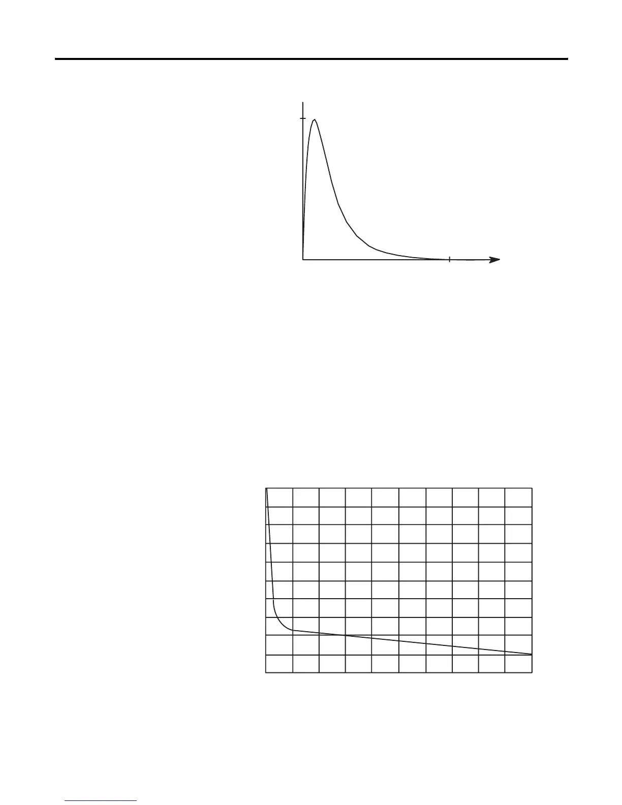
The duration of the transient pulse is proportional to the load
impedance. This is illustrated in the following graph.
Transient Pulse/Load Impedance Graph
Duration of Transient (T)
Time
(On-State Load
Current)
Current
Transient (I)
0
1000
1
2
3
4
5
6
7
8
9
10
1 100 200
300
400 500 600 700 800 900
On-State Load Current (mA)
Duration of Transient (ms)

 Loading...


