Appendix E – Upgrading/Downgrading the System
260
Hardware Reference Manual – Enova DGX 100 Series Digital Media Switchers
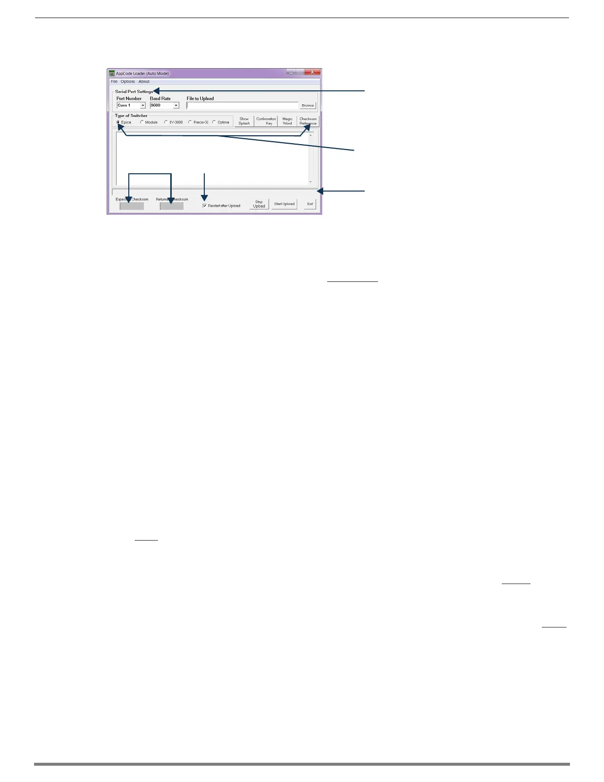
8. Open the AppCodeLoader program.
9. Set Serial Port Settings for your system:
a. Set Baud Rate to 9600
b. Set Com port per your system’s requirements (1-9 are available options)
10. Browse for the “image-v2.x.x.enc” file (downloaded from www.amx.com) to upload.
The “Restart after Upload” check box must be selected.
11. Click the “Start Upload” button and wait for the upload to finish.
The [Expected Checksum] and [Returned Checksum] will match when the upload is complete (update takes about 3 minutes
and says “Upload Successful!” when complete).
NOTE: If the Appcode Loader fails to start the upload, check your Com port and cable connection and click the “Start Upload” button
again.
NOTE: After “Start Upload,” the program changes the baud rate to 57600 and puts the front panel in IOS mode indicated in the text
in the app window, and also on the front panel itself. The front panel LCD shows “IOS Mode Contact Tech Support.”
12. Click Exit.
13. Turn off AC power to the enclosure. Make sure none of the power supply LEDs are illuminated.
14. Replace control panel and tighten the four captive screws – be careful not to pinch the wires when securing the control panel.
15. Apply power to the enclosure.
16. Required – Complete the directions on the following pages to upgrade the CPU, then the enclosure.
TIP: The system’s IP address will be available for 100 Series CPU boards though the control panel’s LCD menu: Function/Setup
Options/Master Info/IP Address. Enter the system’s IP address into a browser on a PC or other device on the same network as the
switcher to launch the System Configuration interface (see page 55).
Removing current CPU Board and Installing 100 Series CPU Board
CAUTION: Do not remove CPU board until you are ready to install the replacement, unless directed to do so by technical support.
Important Information for CPU Upgrade from 8/16/32/64 to 100 Series
Do not transfer SD cards from the currently installed CPU into the 100 Series CPU. SD cards from Enova DGX 8/16/32/64
CPUs and 100 Series CPUs have different functions.
CPU upgrade status will not show on the control panel unless the control panel has been upgraded prior to the CPU
upgrade (see page 259).
Epica DGX SC Optical Boards are not supported within the 100 Series platform; therefore, these boards must be removed
prior to using the new CPU.
After the CPU is upgraded to 100 Series, some boards may not power up. This is normal behavior for boards with firmware
that does not match 100 Series compatibility. Upgrade the enclosure to regain full board power up.
Endpoint devices bound to the replaced integrated Master (DGX 8/16/32/64 CPU) via TCP/UDP connection scheme are not
detectable by the new integrated Master (DGX 100 Series CPU) until the new Master is configured for the IP address used
by the previous Master. (NDP devices appear in NetLinx Studio’s OnLine Tree as unbound devices.)
When a 100 Series system powers up but contains I/O boards with incompatible firmware versions, the CPU will take
longer than normal to boot (15 - 30 min, depending on cage size) and cause the System Status LED to blink red/green.
This indicates that incompatible boards are present and need updating. To shorten the boot time and avoid the blinking
red/green LEDs, the system can be booted with the boards unseated. Then, once the 5002 is online in about 4 min
(indicated by blinking green LED), the boards may be added and upgraded per the normal kit transfer process.
FIG. 130
AppCode Loader
Should match when
upload is complete
Must be selected
Serial Port Settings shown at defaults
Ignore all “Type of Switcher” options and buttons
in this row for this procedure
Progress bar (shows upgrade status)
 Loading...