Appendix E – Upgrading/Downgrading the System
262
Hardware Reference Manual – Enova DGX 100 Series Digital Media Switchers
7. Slowly slide the replacement CPU board into the empty slot, being careful to align the edges in the board guides along the
insides of the slot.
8. Push on the CPU removal tab (FIG. 133) firmly enough for the board to make a good electrical connection (avoid pushing on
the connectors). When the CPU board is fully inserted, its faceplate should sit flush with the back metal.
9. Set old faceplate aside and attach new faceplate provided with CPU.
10. Optional – If ASB boards will be used in the upgraded system, install them prior to applying power to the system for the first
time with a 100 Series CPU installed. For more information about ASB boards, see “Audio Switching Boards - Rules for System
Setup” on the following page.
11. Connect the enclosure (via the LAN 100/1000 port) to your public LAN.
12. Re-attach any cables that were removed in Step 2.
13. Apply power to the enclosure.
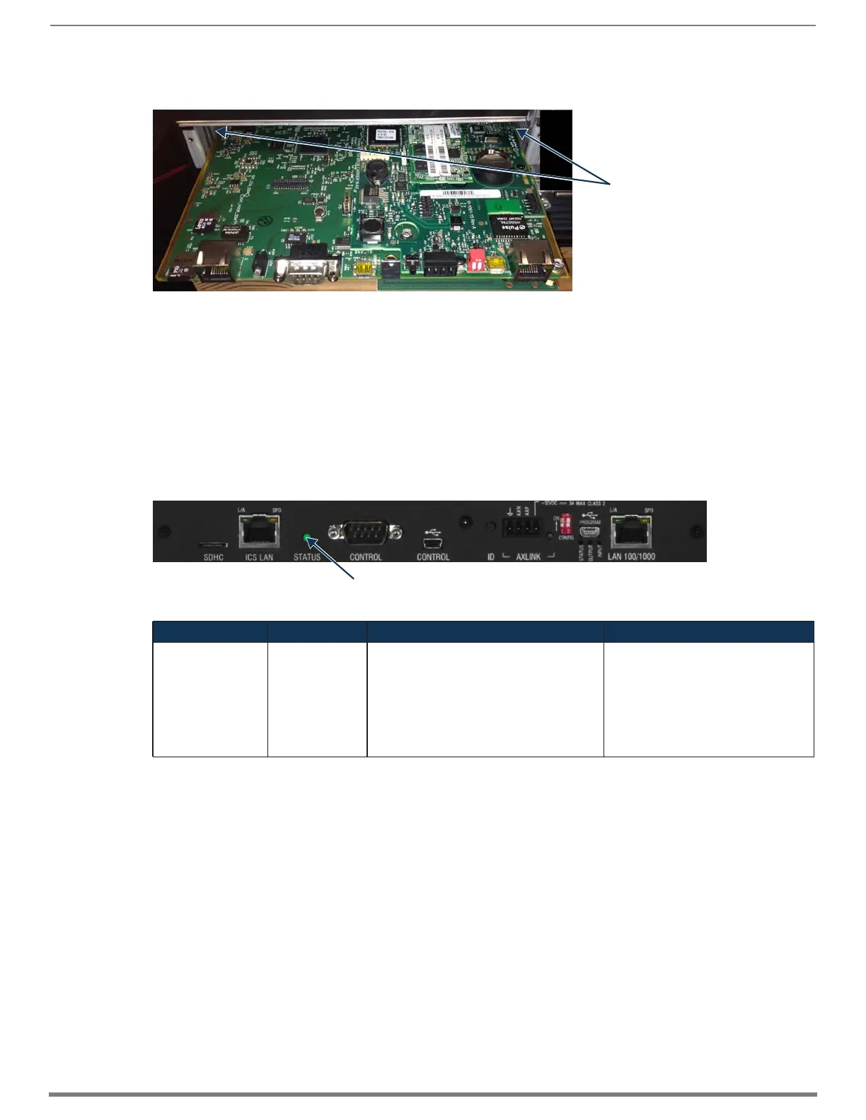
14. Check the CPU’s System Status LED for indications of normal display (see table below).
15. Wait for the 5002 device to come online (15 - 30 min, depending on enclosure size).
NOTE: For information about reducing boot time, see the “Important Information for CPU Upgrade from Enova DGX 8/16/32/64 to
100 Series” section on page 260.
16. If input and/or output boards have been removed from the enclosure, re-insert boards with the system powered and continue
with the enclosure upgrade instructions.
17. To upgrade the enclosure/boards, follow the directions on page 263.
18. Optional (recommended) – Affix the provided sticker to label the product as part of the Enova DGX 100 Series. Enova DGX
Switchers upgraded to the 100 Series are supported by the Hardware Reference Manual – Enova DGX 100 Series Digital Media
Switchers and other documentation marked for the 100 Series.
FIG. 134
Align CPU with board guides
FIG. 135 System Status LED indicator (Enova DGX 800 shown)
LED Indicator Indicates Normal Display Cautionary Display
System Status LED System status • Solid amber during boot load (10 sec)
• Solid green during app load (1-4 minutes,
depending on system configuration)
• Flashing green when ready
Blinking red/green: MCPU is in a fault
state. Power cycle may recover; otherwise,
contact technical support.
(Systems with 100 Series CPU and I/O
boards that have incompatible firmware
use red/green blinking LED to indicate
that enclosure/boards still require an
upgrade.)
Board guides
System Status LED
 Loading...