Installation and Setup
48
Hardware Reference Manual – Enova DGX 100 Series Digital Media Switchers
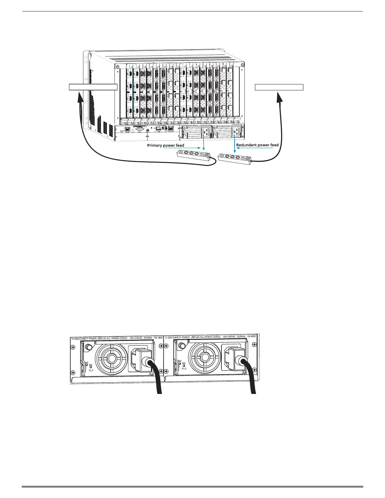
Enova DGX 6400 – To provide adequate power for an N+1 redundant application, connect each of the power supplies to its own
circuit.
CAUTION: We recommend attaching all power cords to a surge protector and/or an AC line conditioner.
Power-Up Sequence
NOTE: Enova DGX 6400 only – Four AC power filtering Ferrites (one per cord) are provided to ensure the system meets or exceeds the
radiated emission requirements defined in standards EN55022:2010, FCC 15.109(g):2014, and ICES-003:2012. To install these
filters, clamp in place onto the power cords as close to the power supply as reasonably possible for the system.
IMPORTANT: Enova DGX 6400 only – If two or more power supplies are not receiving power, shut down power to all power supplies
then restart the system with all power supplies connected.
The following instructions start with attaching only two source and destination devices for the purpose of executing a test switch
(after the factory default switch is disconnected).
To apply power:
1. Attach the first two source and destination devices (attach the remaining devices in Step 9 after executing the test switch in
Step 8).
Do not apply power to the source and destination devices until Step 7.
If connecting devices to DXLink Twisted Pair Boards, the boards require DXLink Transmitters and Receivers. Install the
Transmitters and Receivers between the first two source and/or destination devices and the DXLink Boards (see
“System Setup with Transmitters and Receivers” section in the board chapter and the product’s documentation).
If connecting devices to DXLink Fiber Boards, the boards require DXLink Fiber Transmitters and Receivers. Install the
Transmitters and Receivers between the first two source and/or destination devices and the DXLink Fiber Boards (see
“System Setup with DXLink Fiber, Duplex Units” on page 116 and the product’s documentation).
2. Plug power cords into all of the power receptacles (two or four depending on the system) on the enclosure simultaneously.
FIG. 24
Power setup for complete redundancy on Enova DGX 3200
FIG. 25 Attach power cables to both power receptacles (Enova DGX 800/1600 shown)
Circuit Breaker 1
Circuit Breaker 2
Enova DGX 800/1600 power supplies
 Loading...