Installation and Setup
49
Hardware Reference Manual – Enova DGX 100 Series Digital Media Switchers
3. Plug the other end of each power cord into its power source (if using a power strip, turn on the power strip).
4. Wait 30 seconds.
The Power indicator LED on the Front Panel illuminates green (showing that all redundant power supplies are working). (The
LCD on the Control Panel also illuminates and displays the menu screen.)
Enova DGX 800/1600/3200 – if one power supply is not working, the Power indicator will be a constant red (check
power connections and switches).
Enova DGX 6400 – if one power supply is not working, the Power indicator will be a constant red; if two or three power
supplies are not working, the Power indicator will flash red (check power connections and switches).
5. Optional – Apply power to a control device/system.
6. For systems with DXLink Fiber Boards – Apply power to the DXLink Fiber TX and RX units.
7. Apply power to the source and destination devices.
8. Disconnect the factory default switch and execute a test switch (see page 55).
9. Attach the remaining sources and destinations and apply power to them.
IMPORTANT: Whenever the system is powered down, be sure the indicator LEDs on the CPU are off and the fans have stopped before
reapplying power.
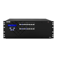
FIG. 26 Attach power cables to both power receptacles (Enova DGX 3200 shown)
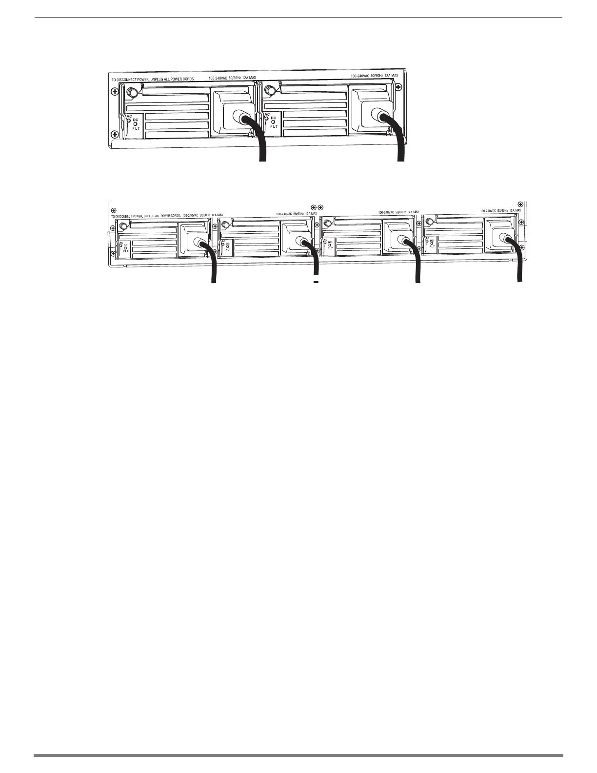
FIG. 27 Attach power cables to all four power receptacles (Enova DGX 6400 shown)
Enova DGX 3200 power supplies
Enova DGX 6400 power supplies
 Loading...