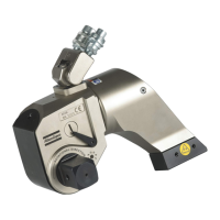
Reassembly of the carrier, flywheel
and electronics unit
Insert the screw (3) washer (4) and carrier spring (5)
in the carrier (6).
Preload the spring by half a turn and introduce the
carrier into place in the flywheel.
Check that the end of the spring is correctly engaged
in the groove. Tighten the screw (3) to the stipulated
torque load.
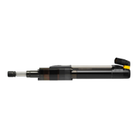
Fit the flywheel (1) to the crankshaft. Lock the fly-
wheel using service tool S19 and tighten the nut (2)
to the stipulated torque load.
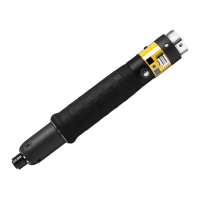
Fit the electronics unit (7) to the crankcase using the
three screws (8) and the washers (9) and (10).
Note: The washer (10) is designed to prevent dam
-
age to the plastic case when the screw is tightened.
Tighten the three screws (8) slightly and adjust the
gap between the flywheel magneto and the electron-
ics unit to 0.25 – 0.3 mm.
Tighten the screws (8) to the stipulated torque load.
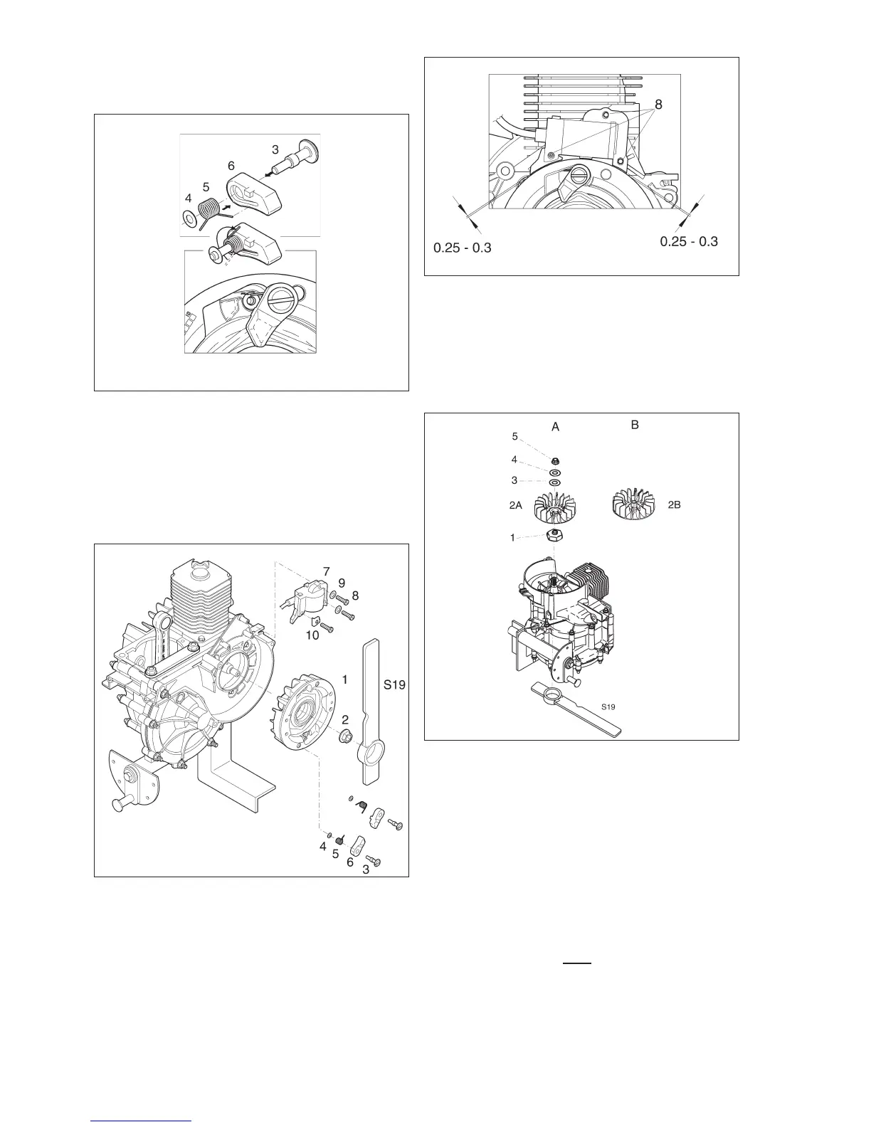
Reassembly of cooling fan
Type A
Locate the hub (1) on the crankshaft taper.
Fit the fan (2A), flat washer (3), spring washer (4)
and nut (5).
Lock the flywheel using service tool S19 and tighten
the nut (5) to the stipulated torque load.
Type B
Note. The crankshaft taper and the internal taper of the
fan must be thoroughly degreased before assembly.
White spirit or a similar degreasing agent must be
used.
Lock the flywheel with service tool S19 and fit the fan
to the crankshaft.
Note. A torque wrench must
be used for tightening,
and the fan must be tightened to the stipulated
torque load of 8 Nm
32
Fig. 57
Fig. 58
Fig. 59
Fig. 60

 Loading...