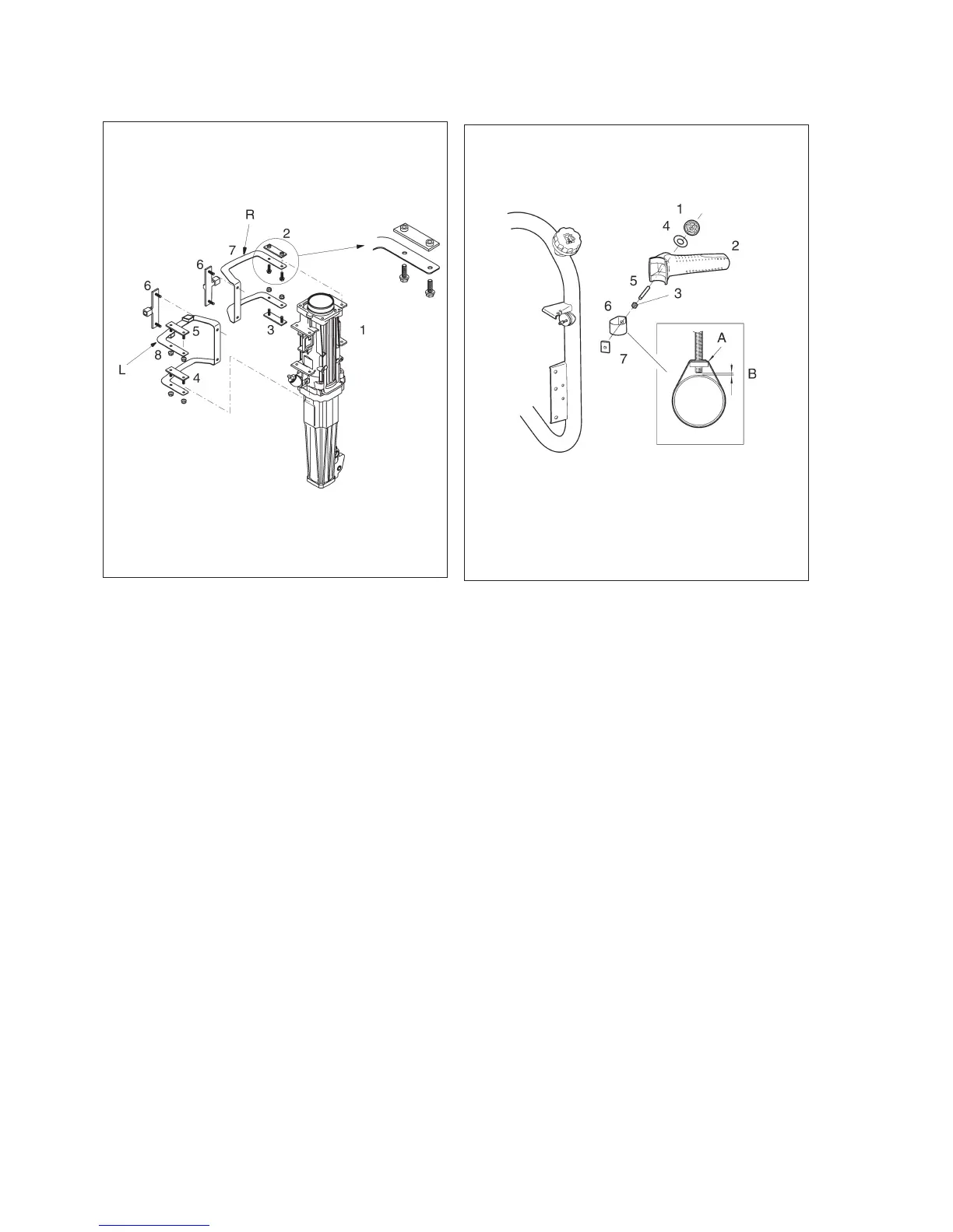
Reassembly of anti-vibration
springs
Fit the leaf spring (7), marked R, on the hammer cyl-
inder (1) with the pressure plates (2) and (3).
Note: The upper pressure plate (2) has captive nuts.
The other three pressure plates (3), (4) and (5) have
captive screws.
Fit the leaf spring (8), marked L, to the hammer cylin-
der with the two pressure plates (5) and (4).
Fit the end stop (6) to the leaf springs.
Dismantling and reassembly of
right handle
Dismantling
Remove the handle locking nut (1) and washer (4)
and lift off the handle.
Undo the nut (3) and remove the stud (5).
Dismantle the handle strap (6) and nut (7). If the
strap is damaged, it must be replaced.
Reassembly
Fit the strap (6) to the tank frame. Place the nut (7) in
the strap (6).
Note: The rounded corners (A) of the nut must seat
against the rounded corners of the strap.
Screw the nut (3) onto the stud (5). Screw the stud
into the nut (7), but not to the extent that it bottoms
against the fuel tank; see (B). Fit the handle (2),
washer (4) and locking nut (1).
34
Fig. 66
Fig. 65

 Loading...