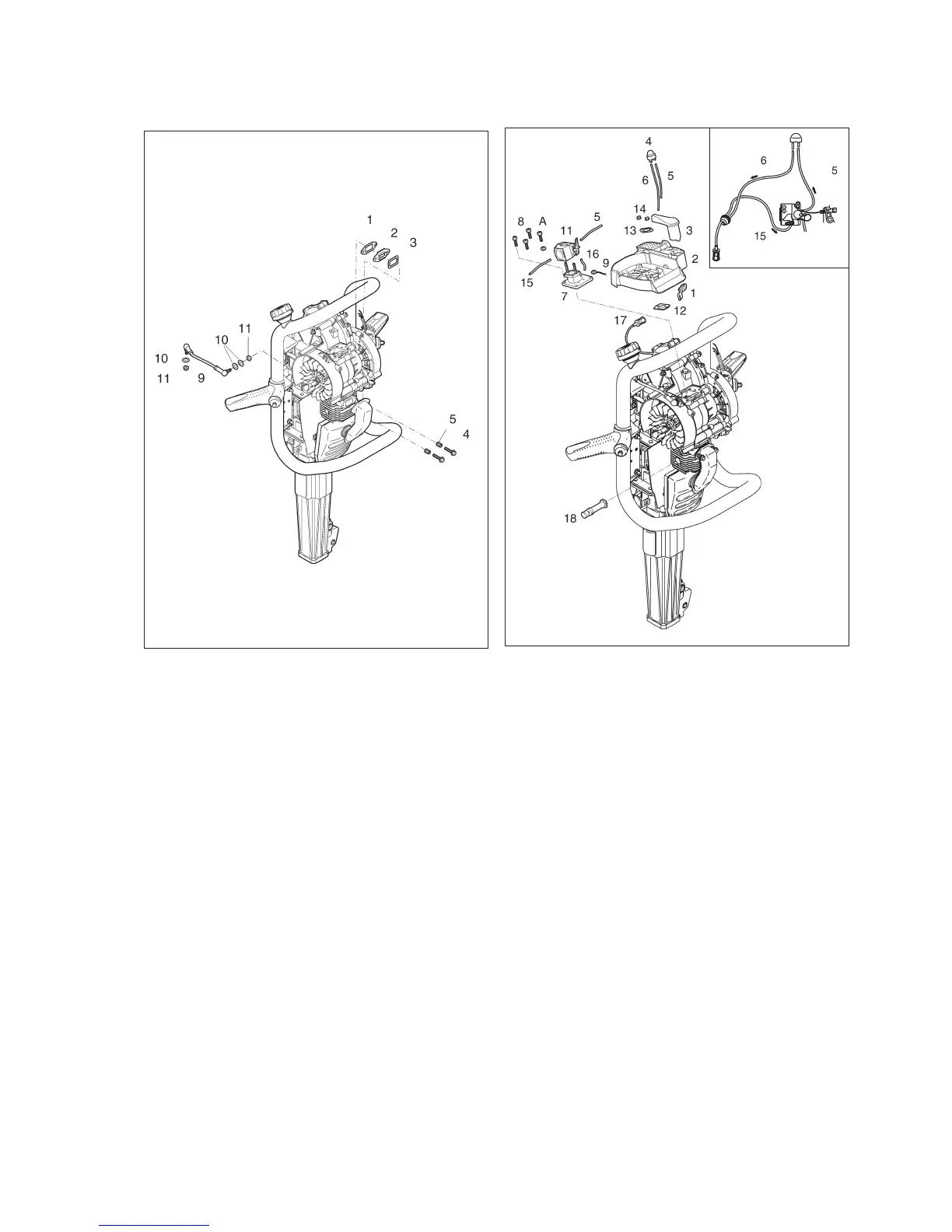
Fitting the muffler and stabilizer
brace
Fit new gaskets (1) and (3) to the insert (2) and
tighten the two screws (4) together with the springs
(5).
Fit the stabilizer brace (9) on the fuel tank and the
enginen. Tighten the nuts (11) and the washers (10).
Push down the handles and check that the stabilizer
brace does not make contact with the engine crank-
case when the end stop is in its lowest position.
Adjust if necessary.
Reassembly of filter housing
Fit the diaphragm valve (7) on the crankcase using
the four screws (8). Tighten the screws to the stipu-
lated torque load.
Note: The stop button earth cable (9) must be lo-
cated under screw (A).
Fit the choke control (1) in the filter housing (2). Con-
nect the choke lever (3) to the choke control (1).
Check that the choke control can move freely.
Fit the venting pump (4) in the filter housing.
Connect the pipes (5) and (6) to the venting pump.
Note: The short pipe (5) must be connected to the
short nipple, and the long pipe to the long nipple on
the venting pump.
Fuel is sucked through the short pipe through the
carburettor to the venting pump and is then led back
to the tank through the long pipe.
Locate the carburettor (11) on the diaphragm valve
(7). Connect the fuel pipe (15), pressure pipe (16)
and venting pump pipe (5) to the carburettor.
Place the gasket (12) on the carburettor and fit the
filter housing. Fit the flat washer (13) and the nuts
(14). Locate the ventilation filter (17) in the holder on
the under side of the filter housing. Fit the decom
-
pression valve, and tighten it to the stipulated torque
load.
37
Fig. 71
Fig. 72
 Loading...