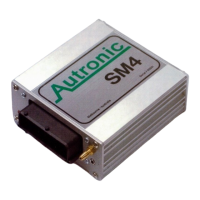
Flying Leads
Locate and connect the following flying leads.
See also main wiring diagram at the end of this manual.
Black (ground)
Locate a good chassis ground and connect the black wires.
Red (12 volt battery)
Locate a source of continuos +12 Volts and connect the red wire. Connecting direct to
positive battery terminal is suggested. Use a 30 A Fuse close to battery.
Purple
The purple wire is the 12Volt Ignition lead to the ECU. It needs to be connected so that
sees 12 Volt only when ignition switch is on and during cranking. This wire does not draw
a lot of current (<0,5A).
Brown
The Brown wire is used to operate the fuel pump, and will deliver +12Volt, ground the
other pin on the fuel pump.
Other wires
They are clamped together for easy finding to each function. Always “ring” the wire to the
SM4 connector to make sure you use correct wire.
Wiring Injectors
The injector wires are clamped together (10 wires), the two brown wires are 12 volt
power and should be split to all injectors. The injectors should be wired in ignition firing
order. Write down your firing order on the main wiring diagram, this makes it easy to wire
the injector output to the injectors.
The injector output sequence can be adjusted in the software under menu Advanced
setup. Consult your dealer.
Example:- 4 Cyl engine firing order 1, 3, 4, 2
Injector output 1 to cylinder 1
Injector output 2 to cylinder 3
Injector output 3 to cylinder 4
Injector output 4 to cylinder 2
Wiring Ignition
Distributor engines
Distributor engine always use Ignition output 1.
1 coil should be selected in the software
Direct Fire Ignition engines
In direct fire setup the SM4 always start with ignition output 1 (not like the
SMC/SM2), and then Ignition output 2 is fired then 3 & 4 (if used).
The ignition output sequence can be adjusted in the software under menu
Advanced setup. Consult your dealer.

 Loading...