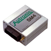
SM4 Manual by MRM-Racing V3.0
Output Channel Electrical Characteristics
The following table describes the electrical characteristics of the output channels when used for
Auxiliary devices such as small solenoids, automotive relays or constant loads.
PUSH-PULL DRIVER 12 VOLT TO GROUND, +/- 1 AMP
PUSH-PULL DRIVER 12 VOLT TO GROUND, +/- 1 AMP
PUSH-PULL DRIVER 12 VOLT TO GROUND, +/- 1 AMP
PUSH-PULL DRIVER 12 VOLT TO GROUND, +/- 1 AMP
PUSH-PULL DRIVER 12 VOLT TO GROUND, +/- 1 AMP
PUSH-PULL DRIVER 12 VOLT TO GROUND, +/- 1 AMP
PUSH-PULL DRIVER 12 VOLT TO GROUND, +/- 1 AMP
PUSH-PULL DRIVER 12 VOLT TO GROUND, +/- 1 AMP
ON IS SHORTED TO GROUND, 4 AMP
ON IS SHORTED TO GROUND, 4 AMP
ON IS SHORTED TO GROUND, 4 AMP
ON IS SHORTED TO GROUND, 4 AMP
ON IS SHORTED TO GROUND, 4 AMP
ON IS SHORTED TO GROUND, 4 AMP
ON IS SHORTED TO GROUND, 4 AMP
ON IS SHORTED TO GROUND, 4 AMP
ON IS SHORTED TO GROUND, 3.5 AMP 9.5 –1200HZ
ON IS SHORTED TO GROUND, 3.5 AMP 9.5 –1200HZ
ON IS SHORTED TO GROUND, 2.5 AMP
ON IS SHORTED TO GROUND, 2.5 AMP
ON IS SHORTED TO GROUND, 3.5 AMP
ON IS SHORTED TO GROUND, 2 AMP
Input Channel Electrical Characteristics
0 – 5 VOLT, WHEN USED AS SWITCHED INPUT ADD 1K PULL-UP RESISTOR
0 – 5 VOLT, WHEN USED AS SWITCHED INPUT ADD 1K PULL-UP RESISTOR
0 – 5 VOLT, WHEN USED AS SWITCHED INPUT ADD 1K PULL-UP RESISTOR
SWITCHED INPUT, SHORT TO GROUND FOR TO ACTIVATE
SWITCHED INPUT, SHORT TO GROUND FOR TO ACTIVATE
SWITCHED INPUT, SHORT TO GROUND FOR TO ACTIVATE
SWITCHED INPUT, SHORT TO GROUND FOR TO ACTIVATE
SWITCHED INPUT, SHORT TO GROUND FOR TO ACTIVATE
SWITCHED INPUT, SHORT TO GROUND FOR TO ACTIVATE
See wiring diagram SM4 Input Switches at end of manual for pull-up resistors.

 Loading...